|
Fifty
years of abuse rendered the old stock latches totally useless. The choice was to go with
new stock latches or something a little more modern. New outside handles/buttons and new
striker plates will run you in the neighborhood of $150.00. Somewhat less if you have some
working pieces. Solenoids and bear claw latches will probably be in that neighborhood,
depending on the brand and type of solenoid (gear motor vrs pull type solenoids). The
latches are generally the same, some a little heavier duty than others.
|
|||
| Since I wanted to shave the door handles and locks, I opted for the solenoid/bear claw route. Of course it goes without saying that the holes for the outside latches and key lock must be filled in and prettied up. So I'm beginning with the bare door after the body work is done. You must also have your doors hung correctly on good hinges with no slop. So before you start hacking up the doors.. rebuild your hinges, hang your doors with new hardware and align them just like a final fit. If possible have the weather stripping installed, although sometimes this isn't possible since you haven't painted the jambs yet. The weather stripping is usually a put it on and leave it type item. It's too expensive to put on and tear up taking it off. The gorilla snot adhesive doesn't give up easily without tearing up the strip. | |||
|
I purchased my equipment from StreetWorks. Other dealers sell them, check the catalogs. From what I have been told, the heavy duty solenoids with a gazillion pounds of pull are not necessary in any but the extreme cases where old, worn stiff latches are being used. The bear claw latches need very little pull to open them. The screw motor actuators have plenty of torque. I first installed the screw motor actuators and they worked fine for a while but eventually wouldn't pull the latch and would leave you stuck in the truck...not good with a claustrophobic wife. What I eventually found out was that after paint and weatherstripping... the doors fit tighter in the frame and the little actuators couldn't do the job
|
|||
|
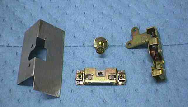
I initially bought two Spal screw motor actuators, two latch mounting plates, two bear claw latches, two striker posts and two adjustable mounts (cage nuts) for the striker posts. |
|||
|
these are the parts you need for one door without the actuator
|
|||
|
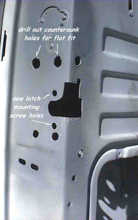
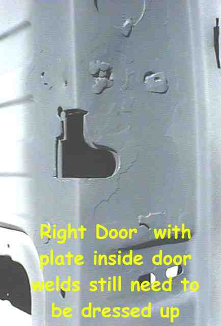
I started by holding the latch mounting plate up against the outside of the door and scribing the latch hole on the corner of the door. I chose to mount the mounting plate on the inside of the door so the cuts will be a little deeper, but this will give you a starting place and you can file or grind the rest after you get started. My new latches were mounted lower in the door than the stock latches so I would have some nice flat surfaces to work with ...the original striker bolt holes and the latch holes will be filled and dressed smooth. If you use your mounting plate on the inside of the door as we did, there are probably two or three countersunk screw holes (old latch mounting holes) that must be drilled or ground out so the plate can mount flush. These can be used for the rosette welds that hold the plate in place. I welded mine on the latch face of the door and on the inside face of the door.
|
|||
|
|
|||
|
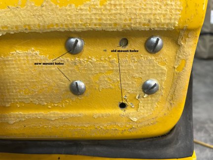
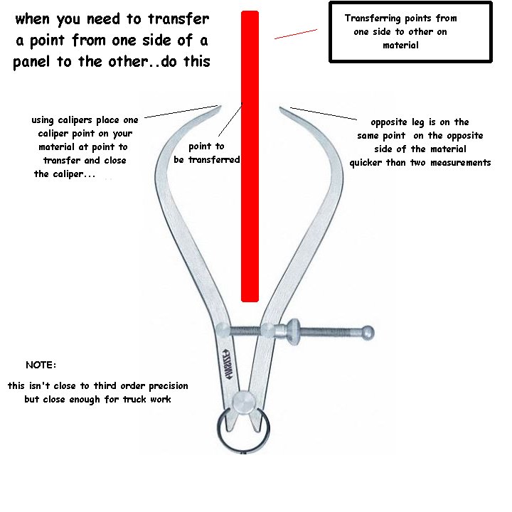
The latch mechanism is held to the mounting plate by hex drive button head screws so the holes for these screws must be drilled through the door facing so the latches can be removed later if necessary. Locating these holes is easy using a set of calipers and transferring the center of hole from the inside of the door face to the outside. Drill them large enough to pass the screw.
The next step is to locate
the position for the striker post in the cab door facing. Mark the position of the latch
cutout in the door on the cab door facing and measure the distance from the inside door
edge to the center of the latch mechanism with the latch closed. This will be your
"set in" distance for the post. Keep in mind, if you don't have your
weather striping installed yet, this dimension might need some adjustment later. Using the
adjustable mounts, you can easily move it an inch
in any direction.
There will mostly likely
(probably, unless you're lucky) need to be some adjustment here after
weatherstrip and final door gap alignment is done, so ream out the holes
accordingly
|
|||
| Mounting the solenoids / actuators | |||
|
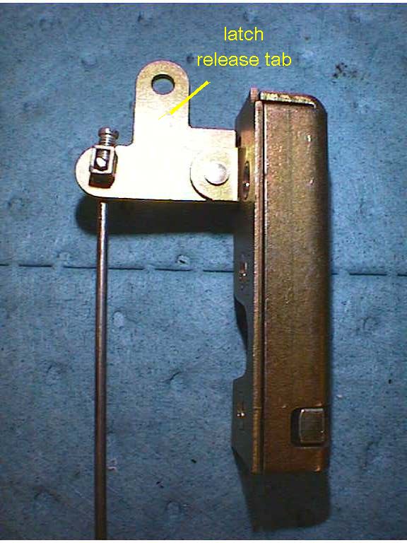
Looking at the bear claw latch you can see that there is a L-shaped lever extending from the top of the latch with two holes. This is the actuating lever for the latch. Pulling down on the lever releases the latch to open. Or pulling the top hole "out" does the same thing
|
|||
|
|
|||
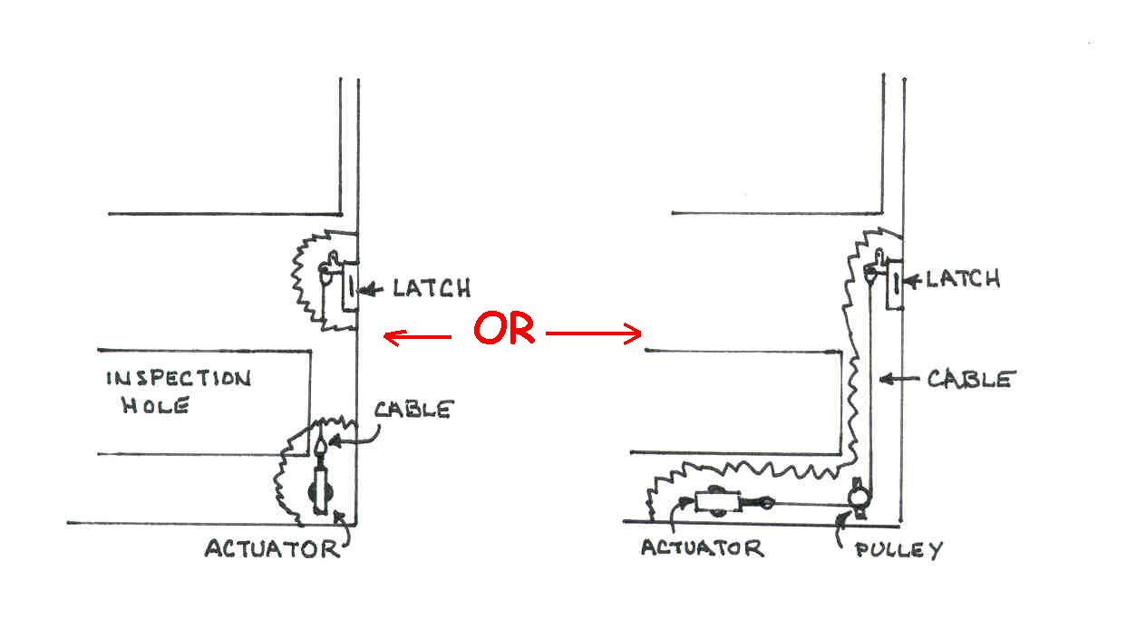
| The actuator or solenoids operate with a pull motion usually about to one inch or less. This is gracious plenty to actuate the latches. These latches actually only need 3/16" of pull to release.. Normally the actuators are located in the lower portion of the door in order to clear the window and associated window hardware/tracks/mechanisms. The easiest mounting is with the actuator mounted vertically and pulling straight down on the lever in the latch. Sometimes in some doors with different window hardware, this isn't possible and the actuator must be mounted horizontally. If this is the case, the retailers offer a kit (or you can scrounge up the parts) with a cable and pulley assembly that will allow the actuator to work "around the corner" or at 90° to the latch lever. | |||
 |
|||
|
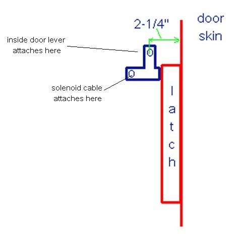
In the large Ford truck doors there is plenty of room for a vertical mount. First determine the proper position for the actuator. I measured the distance from the door latch face to the center of the hole in the latch lever as 2 -1/4 ". This is a little cumbersome, reaching through the inspection hole of the door holding the ruler between the latch lever and the door facing and looking down through the window slot to read the distance. Having a helper here is great especially if your arms are a little short. It's also easier to just lay the latch face down on the bench and measure up to the hole. I scribed a mark on the inside door facing 2-1/4" from the edge then using the actuator for a pattern, I lined up the center line of the actuator shaft on the scribed line and marked the mounting holes on the outside of the door. |
|||
 |
|||
|
If you're using the
smaller screw actuators read the words below...if you are using the larger
heavy duty solenoids most have 4 hole mount plates .... skip down to the red
detail below this
Drill the two holes... And making sure that the actuator is turned so the center line of the shaft is over the scribed line mount the actuator loosely to the door. Now another cumbersome measurement. Reaching back through the inspection hole, measure the distance from the hole in the latch lever to the hole in the actuator shaft. Your connecting hardware has to be that length. Mine was 14-1/2". There are several methods for connecting the two. The actuators come with a flat drilled bar, a rod and some strange hardware. I played with this and was never satisfied with the fit...it was sloppy. You can use light gauge cable with cable clamps. This is easy to install and adjust to remove the slack. I finally settled on a straight 1/8" steel rod with a 90° end on each end. I fabricated a set of clamps from some old electronic terminal strips which are nothing but a small piece of 3/16" square tubing with a set screw that clamps the rod in the tube. Before I install the latch in the door I installed the rod on the latch actuator lever and attached the clamp. Then installed the latch in the door ....slipped the rod through the actuator shaft and added the clamp...simple, clean and no slop in the movement. Be sure to leave a little space between the levers and actuator shafts and the clamps. You don't want the assembly tight enough that it binds or the actuator sticks in the "pulled" position instead of returning to the top. Another problem...be sure that the end of the rod faces the outside door skin (on the latch end) it's a tight squeeze between the latch and the inside door frame and it could hang or bind up there.
|
|||
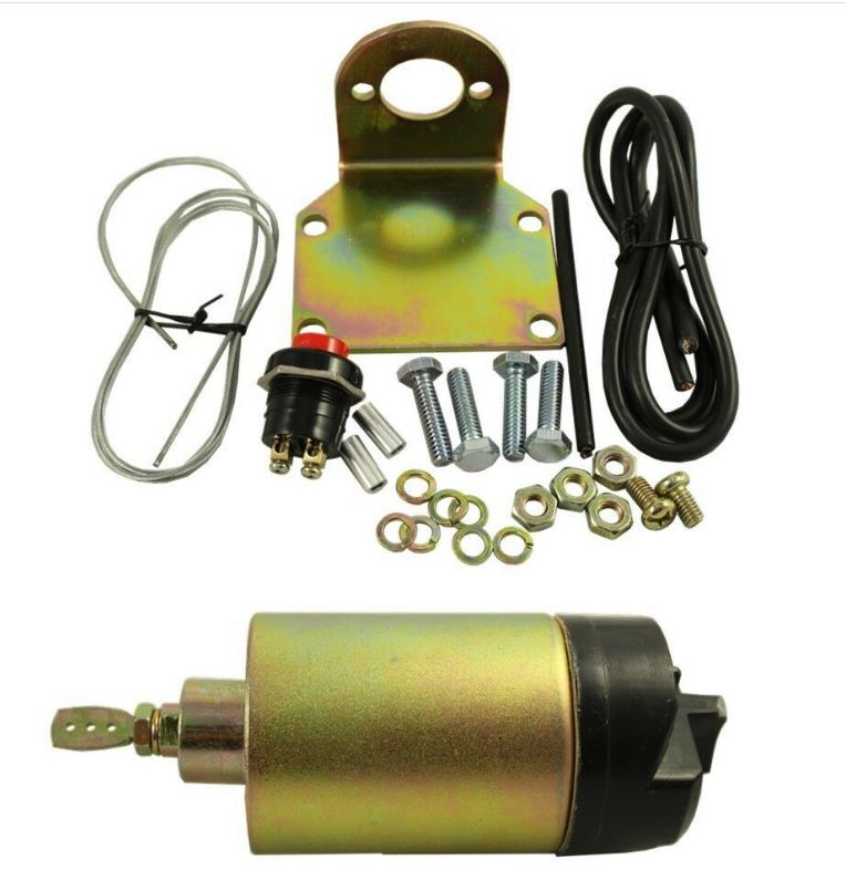
|
These are the solenoids I am using. 100# pull (they claim). I'm only using the mount, cable/clamps and solenoid as my wiring is already done. I didn't have an accurate way to check that claim, but I put the solenoid in a vice, connected a cable to the plunger and pulled back on the cable.. My 210# body could not stall the solenoid when activated... that's plenty for me. the old smaller screw motor actuators operated with a little "buzz" and I was never really happy with them... (that comes from an inexperienced builder not knowing what to buy, believing the advertising and cheaping out). The new solenoids when actuated make a very loud "clunk" and a hard pull to pull the latch lever. Much more gooder.... So first....I removed door upholstery panel and inspection cover then the old actuator and linkage to the latch.. I also had to disconnect all the window "stuff" motor, track and window to get enough room to get my fat hands into the space to work. I just dropped it down inside the door. The inside handle and latch rod worked out fine for fit and with a little fabricating and a spring... a little drilling I got the latch working properly with the inner handle. (*More detail on that later in the page) Next came the solenoid. Of course the mounting bracket was totally different and four new holes were required which meant removing the lower carpeted part of the door cover...Got it mounted up with minimal blood loss... that working in the bottom corner of the door is fun... small and blind work. You can hold the solenoid bracket in place inside the door and using the caliper method transfer the hooles to the outside for drilling. I did one hole this way then made a template for drilling the others. (see sketch of caliper method down below) With first install I used 1/8" rod arranged around window mounting... this time I opted for the cable that came with the solenoids and it was much easier to work with... although the cable was 1/16" cable and the hole in the piston was 5/64s. I drilled the piston hole a little larger to get the cable to pull through easily. I attached the solenoid cable to the lower latch hole and the inner handle to the upper... I tested it about 78 times and both work properly... now... just put all the window stuff back and adjust it then replace the upholstery...and move to drivers side...only addition on the drivers side will be the hidden pull cable to attach to open the door in case of dead battery. |
|||
|
|
|||
| My old hot rod buddy that helped me build my truck told me at the beginning... "Everything you change...changes three more things all by itself" This has been true every single time I've changed something. This project involved having to move the arm rest to accommodate the new inside handle... drill new holes in door and add rivet nuts and punch three new holes in upholstery panel... luckily the arm rest covered the old holes (phew !!) | |||
| ADDING INSIDE DOOR RELEASE HANDLE | |||
|
My wife is a little claustrophobic and she
wasn't comfortable with no manual way to open doors should we lose battery
power. Which IS a fair concern if you are in the truck with windows up
with a dead battery (i.e. Alternator dying and the battery running
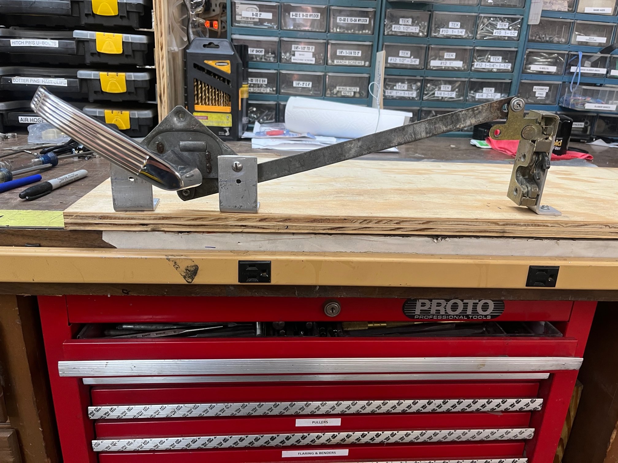
down getting to your destination without realizing it) Solution... manual release on door latch.. inside handle. I bought the hardware at the GrandNationals in 2020...door handle assembly and the door handle but just put it on this year. My previous statement about change applies here also. I have power windows and use the upper handle assembly hole for the upper track mount point for the window track... So first I had to remove that bolt and find a work around. I had dropped all the window apparatus down in the door to have room to work on the new latches/solenoids, so the work around had to wait till the handle install was done. I mounted the handle assembly in it's original spot with three stainless bolts and then worked on the connection to the bear claw latch. I tried several approaches but finally settled on a bar/spring connection that did the job perfectly. I mocked up the latch hardware but could never get a combination that worked the way I wanted...
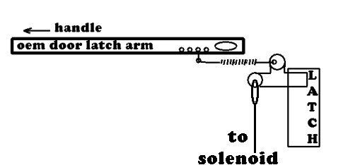
the latch only needs 3/16" to trip and I wanted a little more motion in the handle (slop) to prevent accidently bumping the handle and releasing the door... The original latch arm length was actually very close so I didn't change latch arm length...but I could never get a connection that actuated the latch with the proper amount or initial movement of the handle.. and if I tightened things up, it locked up. So you had to allow some slop in the rigging... I don't like slop. My solution was drilling a series of holes along bottom edge about 1/4" apart and used a spring to connect the latch arm to the latch lever at the top hole...using the holes I adjusted it using the holes so the handle wouldn't pull the latch until the handle was lifted about 1". Sorry, no actual pictures... I was busy trying to get things to work properly. So a sketch will have to do.
Now the passenger side door has two ways to release the latch... solenoid and handle...wife happy and it only took about a week :-(
The
fix for the door handle/window track was easy I removed the upper door
handle screw and changed it out for a self tapping sheet metal screw which
passed thru the handle bracket and screwed into the window track and secured
both together. |
|||
| That's about it, there will be a period of adjustment after weatherstripping and door alignment..so slot all your mount holes..... It's nice to hear that "clunk" when you push the button and the door pops open a couple of inches... | |||
|