|
Installing an
IDIDIT Column In a '53 F-100 by John Niolon |
 |
|
Installing an
IDIDIT Column In a '53 F-100 by John Niolon |
|
| Everyone that visits the FTE forums knows of my
tendency to ‘redo’ portions of my truck …even before I’ve finished it
! And, I get a fair amount of grief about it, but that’s ok…as long as
it’s my money and not theirs, I’ll pretty much do what I want. We all know the “Put the Volare in… take the Volare
out… Put the Mustang II in” saga. The main reason for the swap was a
problem with header clearance. I couldn’t make my headers fit with the Volare
clip in place. (The other reason was the M II unit was just so darned pretty)
Anyway ??? The Mustang II unit is in and in re-installing the steering linkage I
then had a clearance problem with the steering column. I had installed a mid-80s Caddy tilt/slide column and it
worked perfect with the steering box of the Volare… but since the Mustang II steering
box is lower and more centered…. Well… the headers were in the way.. Not a
big deal, slide the column over a bit… but then I messed up !! I started
thinking !! I started thinking that I really didn’t like the look of the caddy
column… kinda big and bulky and after a little more investigation, I could see where
the ‘innards’ were worn and could probably need replacing. I started
looking through the magazines and catalogs. I found a rebuilt GM column for a few
hundred bucks, but I’d still have a ‘used’ column, rebuilt or not. I
turned a page and like a kid, something shiny caught my eye. It was a Flaming River
Chrome Column displayed diagonally across the page and it was whispering my name. A call to the toll free line got me all the details… I
needed the column with the shifter on the column and with tilt AND with a 1”-48
spline shaft. My original set up had Borgeson U-joints and vibration dampeners
splined for a GM 48 spline shaft. Any of you that have priced Borgeson
‘stuff’ know it ain’t cheap and I didn’t want to waste what I already
had. Flaming River said “No Problem” but it’s an extra hundred bucks
for a “special order”. I asked the rep why if they were building the
column anyway, couldn’t they just put a 48 spline in ?” seemed like a
reasonable request…and it was… for a hundred more bucks. This was already
an expensive item, running a few hundred bucks more than I’d imagined. Time for
PLAN “B”. Plan B was a call to IDIDIT. We went through the same
specifications and again the response was ‘No Problem”. Then I mentioned
the 48 spline part ??? I tensed up waiting for the added charge. The rep
replied “No Problem, we’ve got to build it anyway”. Exactly what I
wanted to hear. They told me they had built columns for this model before and what I
needed was a 30” column and about a 3” drop at the dash. So, that’s
what I ordered. Shiny chrome tilt job with column shift, and wiring built in for
(future) cruise control installed in the turn signal lever. A couple of weeks later,
as I pull in from work, I see a box is leaning up against my garage door ( an expensive
box that UPS left unattended.. made me a little apprehensive, but it did arrive). I checked out the contents and everything was there and in
good condition… very well packaged and protected. It was so pretty you hardly
wanted to touch it and get fingerprints all over it… The installation
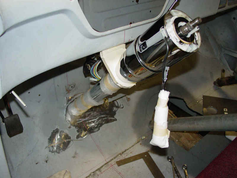
follows… When I had originally installed the GM unit I had cut a large
opening in my new floorboards to make the install a little easier. I had made
a cover plate after it was complete. So, un-installing was easy. There was no
linkage to disconnect, just two bolts on the floor and two on the dash and the old column
was out. The first step was to determine how much to adjust the column left to clear
the headers and patch/redrill the floor. The old GM column shift lever was fixed on the shaft so a
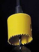
larger hole was needed to get thru the floorboard. The IDIDIT has a removable shift
lever so you can cut the floor hole just larger than the column diameter of
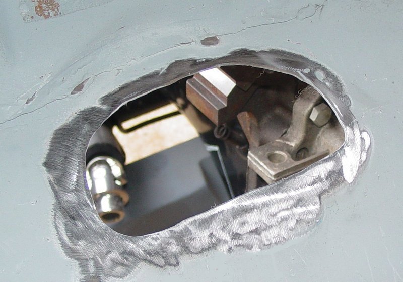
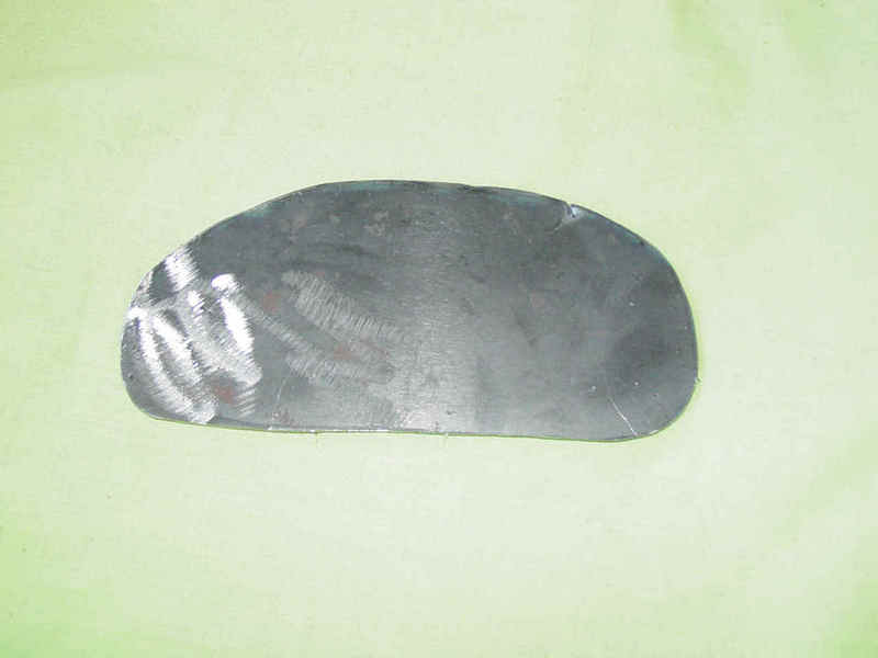
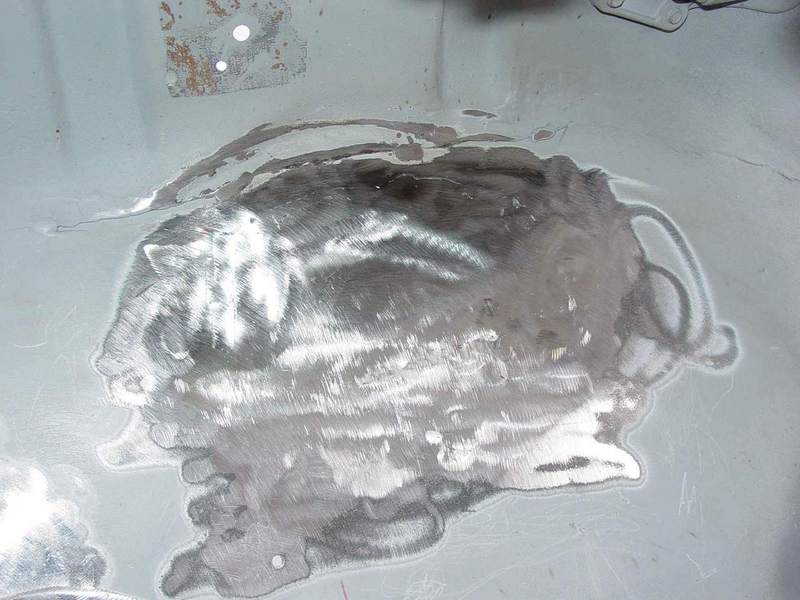
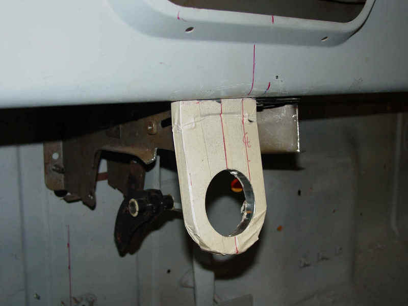
2.25”. A 2.5” Greenlee punch made easy work of the hole. But I’m getting ahead of myself. As I said the hole in the floor was rather large about 6x4…
Sooo, I cut a patch panel to match the hole,
welded it in and started over..
Now we have a clean semi-un-altered floor to start
with…the next step is deciding where it will enter/exit the floorboard. If your
floorboard is original and has the large opening already cut, you can probably fit it in
this hole with no problem. Many of the older trucks had a steering column angle that was
too steep for comfortable cruising. Experiment a little with your column angle. Choose an
angle that feels comfortable when you’re sitting in your normal driving position.
Consider your seat position, distance to pedals and most importantly…. how your arm
hangs on the window frame. You have to have the proper "attitude" when cruising
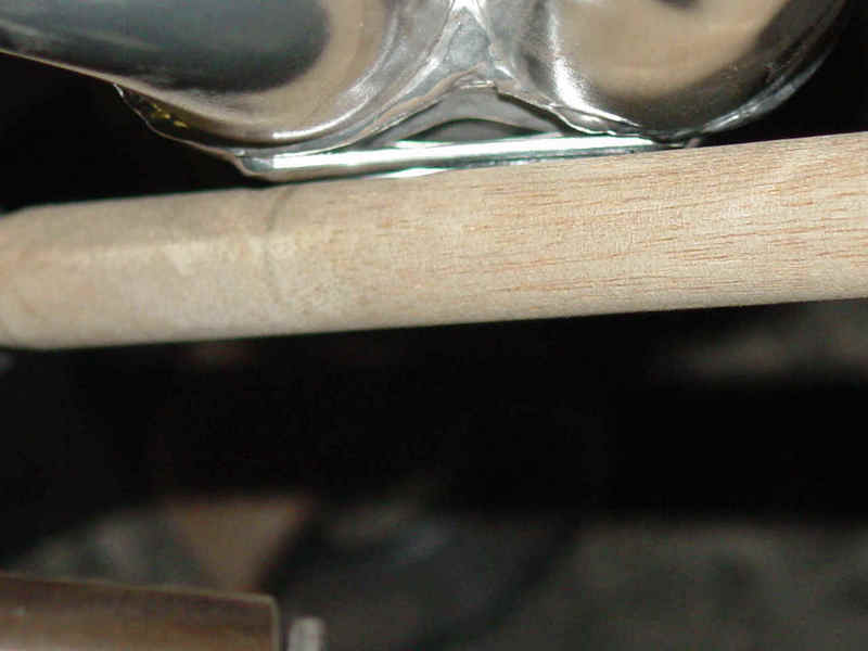
and you can’t do that without the proper stance. I’ve seen articles showing a broomstick or a piece of
conduit and a pie pan mockup. Using the column itself is a little cumbersome.. it’s
too long without the hole in the floor and it’s heavy and hard to handle.) It helps
to have someone to assist you at this point. Move your dummy column around…try
different heights… get comfortable. When it "feels" right have your helper
take some measurements and mark the floor where the column will exit. Measure the
distance from the floor up to your “wheel”… measure the distance from
the center of the column… perpendicular to the column shaft up to the underside of
the dash (for column drop length) (Remember, if your column has tilt also it will make
your ride more comfortable). This measurement process should give you the probable
vertical (up and down) center of the cut out in the floorboard. You probably want the column to enter the floor perpendicular to the floor… If it goes in at an odd angle ( angling to the left or right) it just doesn’t look or feel right… I then found the centerline between the column mounting holes under the dashboard and then using a framing square and a straight edge…. Projected this line down to the floorboard. This should give you a good center horizontally (left to right). On the outside of the cab, I used the centerline of the steering shaft on the rack. A little ciphering and measuring showed these two lines to be within the operating limits of the universal joint. No problem… linkage will handle that easily. To give me a better clearance on the header collector I moved my column 1” to the left. It didn’t affect the feel and the column still looked centered (pretty much) in the dash. My original center line on the floor was moved 1” left and of course, this moved my mounting points to the left in the dash so new holes needed to be drilled.
Well, actually your next step is to wrap the column drop and
the column to protect them… ESPECIALLY if they are chrome or polished. I
covered the drop with 2” masking tape and the column with foam packing material.
I know, you’re careful, but I can almost guarantee a nick or scratch just
where it will show…. Take the time… do it . Now, bolt up the drop to the dash board. For 99% of the applications… you find the
center of the dash panel and attach the drop with two bolts thru the lower edge of the
dash…most times the original drop holes will work our for you. Since mine was offset slightly I had to adjust for
that and drill new holes.
One thing we
haven’t done is secure the column at the floor.
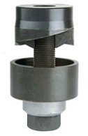
I had used a fabricated floor mount before from a piece of angle and a u-bolt…
worked just fine.
As far as
securing the column at the floor right now… I would wait till I had all my linkage
connected, column at the perfect height THEN tie it down at the floor… just a
personal preference… you might think differently. So now you got it in place… it’s time to connect it to the steering box. At this point your install might differ from mine physically, but not in theory. You might have the stock suspension or a Volare clip or a Mustang II… the only difference is the number of u-joints and length of shafts you need to make it work. I had already purchased a Vibration dampener and universal
joints for the Caddy install and dropped a good bit of change. I wanted to reuse them. I was able to order the column with the 1”-
48 spline shaft to match my vibration dampener so I thought I was ready….. WRONG!!!Will
I just never learn to look ahead ??? After starting
to mock up the linkage I found that because the box on the rack set further to the right
than the Volare box did, it caused some linkage interference with the header collector..
Well, this
isn’t gonna work !! There were a couple
of work-arounds but none were really feasible. One
was a more complicated linkage with a bearing support (which I really didn’t have
room for) and another u-joint then a funky angle to the steering box. The other was to lengthen the steering
column shaft. I’ll interject here that
ordering a 33” or even a 36” column would have cured the problem… so heed
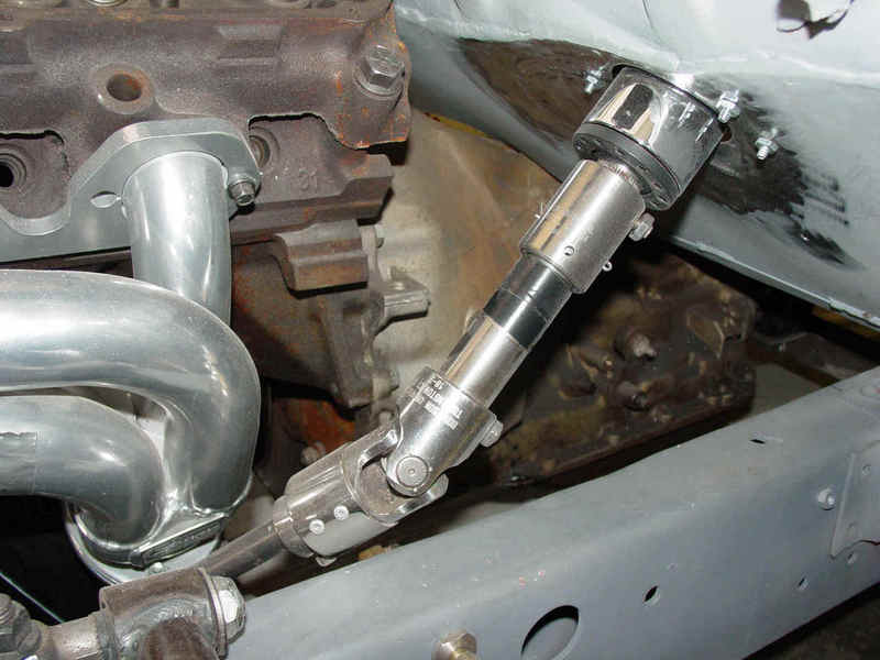
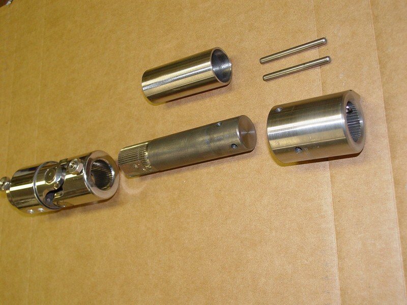
my words… look carefully at your linkage situation before ordering your column. I talked to a master machinist at work... he's 80 years old and this guy can make anything! (Well, I found out..nearly anything). When we discussed making an extension with a 1" - 48 spline female end and a 1" - 48 spline male end ?? Well, he said he probably wouldn't live long enough to make it a perfect fit on the column end...half a tooth off and it won't fit.A bunch of calls and internet searches looking for 48 spline shafts left me with no solution… finally I called Ididit back…. I knew they had couplings and 1”-48 spline shafts… even if I had to buy a complete shaft it might be worth it. I told the tech guys my problem… emailed them pictures and this is what we worked out (with my machinist buddy’s help). Borgeson offers a sleeve type coupling with 1”-48 splines on one end and smooth bore on the other. Ididit has a 1 foot section of 1” shaft with 48 splines that they don't show in their ads... (what for, I wonder ?) anyway…parts were shipped and after mocking up the coupling to the column and building up the other end from the steering box up to the vibration dampener, I calculated the length of the intermediate shaft and presto… we knew how long to cut the shaft to fit. The shaft and coupling already had a good slip fit so my machinist buddy cut the shaft to the proper length and cross drilled the shaft and coupling for double roll pins. Since all my Borgeson parts were polished and pretty… my machinist made a stainless sleeve that fits over the 1” shaft.. The coupling and the sleeve will be polished to match and everything will be shiny… we like shiny Here is a
picture of the extension in place and an exploded shot of the parts. Ignore the tape on the sleeve in the first
picture… it’s holding the roll pins there so I don’t lose them. I mocked up
the extension with a cotter key holding things together.
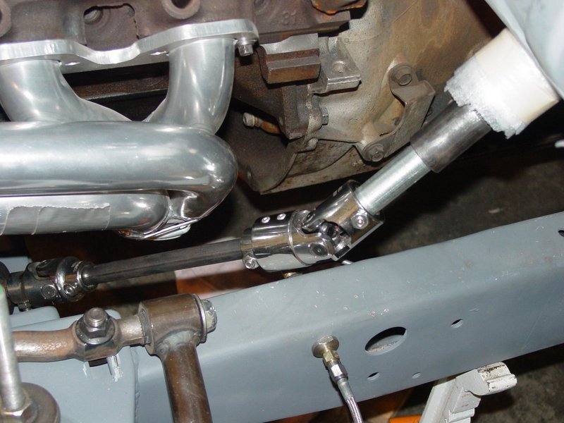
SO, now we put
all the extension parts together, added the vibration dampener, installed the shaft down
to the universal joint on the steering box and tightened everything up. Next we turned the wheels and watched the linkage
closely for binding and looseness and found none. When
I was happy with the linkage, I tightened up the floor mount inside the cab and the column
drop screws. This secured everything. I sorta glossed
over the linkage components but every install is different.. the U-joints and vibration dampeners can be bought
in several different configurations.. smooth
bore, Double-D shafts, splined in both �” and 1” diameters… even
collapsible columns in case you’re concerned with your impact with the steering
column. Borgeson’s catalog and web site http://www.borgeson.com/
have a wealth of information and list all their components.
My best
recommendation is to buy the end connectors (u-joints)
then figure out the middle… some installations will be a simple shaft
between the two ends, some will require a third u-joint in the middle. If this is the case, you will HAVE to install a
bearing support to hold the middle joint in place, else it will ‘wrap’ and lock
up on you. Not a good thing when you’re
trying to steer. The techie guys can lead you
to the proper components…listen to them. I haven’t
chosen a steering wheel yet…. That will come when I get more into the interior design
of the truck.. The stock Ididit column will
accept a gm wheel and other aftermarket units with the proper ‘adapter’. I had an old Chevy wheel that I used for mock up
purposes. Here’s what the
‘almost’ complete install looks like, still have to hookup the turn signal lever
and steering wheel… but the column is complete.
The install would be the same on a Flaming River or salvage yard column with the
mounting being a little different but similar. The column
comes with a standard GM wiring harness plug and most of the wiring kits in the
aftermarket come with the mating socket so the wiring of signals and horn and such is much
simplified… Although the cost was significantly higher than the original Caddy column, I’m much happier with this install. The steel columns start around 400 bucks and go up as you add tilt, chrome, special wiring, etc… the column drops are around 40 bucks and up and the linkage pieces depending on finish could be 30 dollars up to 125 each. It’s not a cheap addition but it adds a lot to the finished look… If you’re looking for practical ‘just steering’ it is quite a bit cheaper with plain steel paintable columns and plain carbon steel linkage pieces. Your imagination (and your Visa balance) are your only limitations
|
Boilerplate denial of liability statement… i.e. the fine print This installation is something I did to put parts of MY truck together. It is not patented, engineered or even perfect… it is what it is, a home done install. I’m sure there are alternatives to this design some even better/cheaper/easier, I just didn’t think of them or warrant them necessary... there are several similar units on the internet waiting behind Google for you to see/copy/build…(just like I did) This work was done by me and for me or by friends who were nice enough to help me out. I only ask that if you reproduce it give me credit for it and if you make money from it… give me my percentage. Since I have no way of knowing your level of competence, welding or cutting skills, mechanical ability or estimated intelligence, there are no guaranties or warranties either verbal, written or implied with this article. Along with this article I am giving you absolutely free of charge…that’s right ! FREE !!...the liability, total and complete liability for the use or misuse of this contraption (and installation method) will be yours and yours alone. It belongs to you and keep that in mind… I am in no way responsible for any damage, injury or embarrassment you may suffer from the use of my ideas or my methods. If it doesn’t look like something you’d be comfortable doing… don’t do/use it. If you’re not intelligent enough to make that decision about your comfort level… ask a family member or friend.. but here’s a hint… if you have to ask someone… don’t do it ! Pictures were made at different stages of construction and all assemblies in pictures may not be complete in each shot. I.e.. a picture showing ‘some parts’ only means that it was not finished, but I’ve tried to make the idea complete to the best of my ability. If you have questions or see mistakes or problems, let me know by e-mail and I’ll make the corrections if possible.. Use these ideas at your own risk. Modify them at your discretion and to suit your purpose. Your mileage may vary, batteries not included, much assembly required... wait one hour after building to enter the water, additional charges may apply. not all applicants will qualify for advertised A.P.R., for ages 10 to adult…side effects are comparable to placebos. Do not take drugs when building or operating machinery. JUST SAY NO. Copyright . 2012 John Niolon, All International Rights Reserved. This document may not be copied or published without prior written consent of the author- jniolon@att.net |