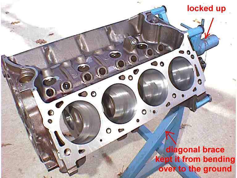
THE BEST DAMN ENGINE STAND THAT MONEY CAN'T BUY
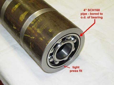
<As I stripped the engine of intake, heads, oil pan and water pump… I finally removed enough weight (about 250 #s) to force the stand to let me roll the block over to get the crank out and punch out the pistons… the bare block was just about the max that my old blue stand could endure. Plans were beginning to come together for a replacement. Looked for stands on the internet. About all I found were pictures of stands for sale… and one lone place that sold plans for a stand. I guess liability enters into the equation here and most people just plop down 50 bucks and buy one that won’t do what they want to do. Those available in the stores weren’t any better and I quickly decided that I didn’t want to invest the cash necessary to buy the stand that would do what I wanted and needed. Good commercial stands are very expensive and that is money I take OUT of the truck budget for non-truck parts. Plan B looked like the way to go. If you’re going to build one… build one that will handle anything short of a Caterpillar, Cummins or a de Havilland. While this stand certainly isn’t built for the large Diesel engines… it will surely handle any normal truck/car engine you can hang on it. The first criteria was something that could be turned easily and have a substantial footprint to prevent tipping or falling over when being turned or moved around the shop. My thinking was that turning easily required bearings and a stout enough shaft to prevent deflection and bending. I discussed this with several folks that know how to build stuff… One of which was a machinist… old school guy in his 80’s who had worked for 60 years in the trades, mostly in steel mills where big stuff is made and destroyed and remade. His suggestion was to find a large enough diameter pipe with sufficient wall thickness… stuff some bearings in it and turn a solid shaft to fit the i.d. of the bearings. Here’s what we came up with and how we put it together. Note here… This stand was to built from ‘available’ resources with hopefully no cash outlay. If you have a reasonably well stocked scrap pile or material hoard, you can do this with very little money leaving your hands. A 10” piece of 4” Schedule 160 pipe was found on the scrap pipe. It’s wall thickness was .531”. We located a stash of old unused bearings … did some measuring and found two alike with a o.d. of about 3.5” and an i.d. a little less than 2”. Mr. Johnny (the machinist) turned the pipe to give a nice tight fit on the bearings and we pressed them in.
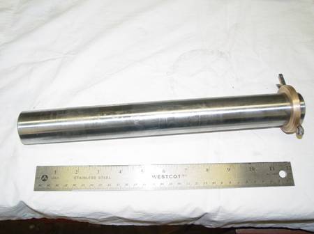
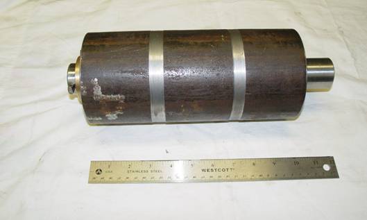
Next he turned down the shaft to match the i.d. of the bearing(less a fuzz) and tried it for fit…perfect.
The two pieces were mated to give us this…
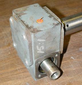
So, that’s the basic rotating assembly. The engine mount plate will be added on one end and a gear drive on the other. The next step broke my rule of zero expenditure. I located a right angle gear reduction box that would work but had to give the owner twenty dollars for it. It’s a 15:1 ratio box and the input/output shafts could be adapted to work for this purpose. NOTE: the gearbox isn't a necessity. You can just turn it by hand/lever and fab up a way to hold it in place... but the gearbox drive is cool.. and you just gotta have a cool engine stand, right ???
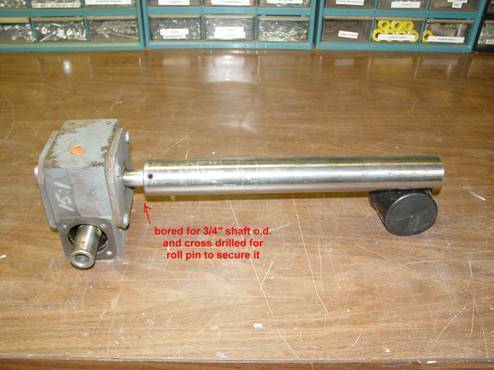
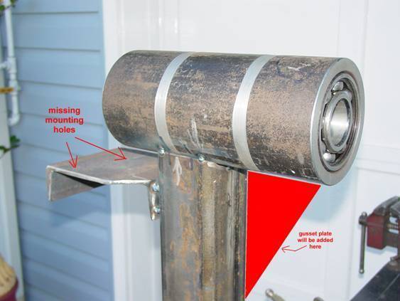
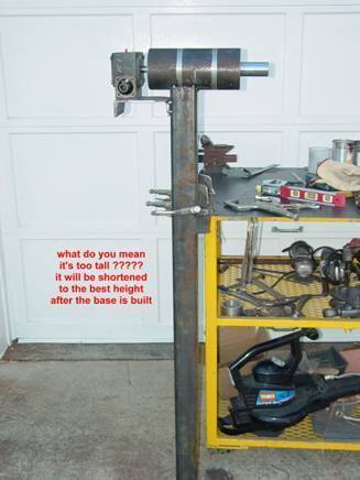
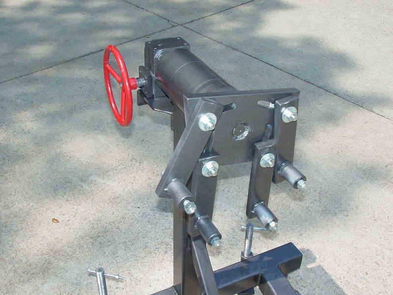
Another favor was used to get the stand shaft bored to fit the output shaft of the gear box..and cross drilled for a roll pin, and here’s what we have. This is a low torque application and the roll pin should work nicely holding everything together . Next came the stand portion. Again, trying to use available materials… so looking around ...I spied over in the corner… 4 pieces of 3” square tubing with a nice thick wall. It looked like it really really wanted to be an engine stand. I plan on tacking everything together first before final welding. I started by coping the end of one piece of the tubing to match the circumference of the 4” pipe. After a lot of cutting and grinding I finally got an acceptable fit for welding (never been very good at coping). I set the tubing up and clamped it to my welding table then plumbed it both ways. Next… set the rotating head on top of that and got everything plumb and level… A little grinding needed here and there till I could tack weld the head to the tubing…making sure it remained plumb and square and level. The gearbox/shaft were put in thru the bearings and everything moved as designed. Then I added a base for the gear box. A piece of 6” channel iron about 5” wide worked perfectly for the base… and it was tacked to the tubing also. Here’s the first screw up of the build… before I tacked the base plate on the tubing I should have drilled the mounting holes for the gear box… that comes from trying to beat the dark and get finished… so, You cut it off, drill the holes and remount… if that’s all I screw up, I’ll be content
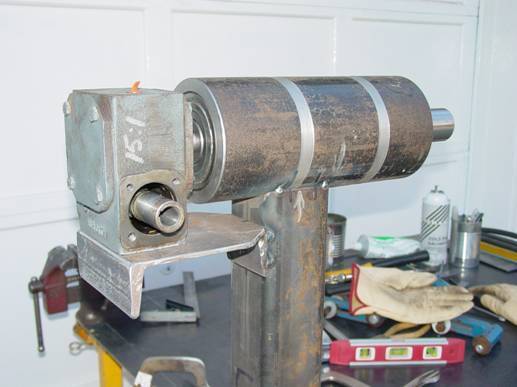
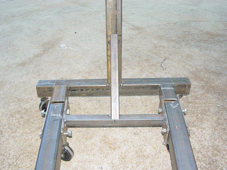
So... to catch the pictures up with the text …. Here’s where we are now
You’d think I’d discuss making the engine mounting plate here, huh ? Well I can’t. It’s not built yet… I’m getting the plate cut on a CNC plasma table that isn’t installed yet… it will come later.
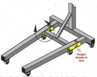
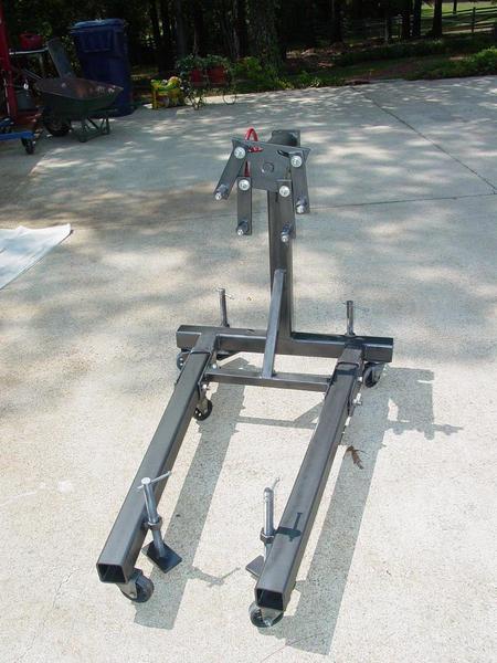
NOTE: the parts above for the head section are fairly precise and need some measurement accuracy and machining skills… the base below is a little more forgiving, although the closer you measure and drill the better things fit together… and won’t look or feel so cooty-bobbed. The design I chose for the base is what I consider the most sturdy.. two legs (instead of one) extend under the engine and give the stand good balance and support. They will better resist tipping as well as roll more easily.
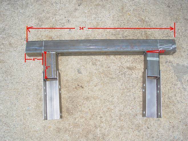
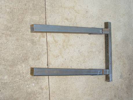
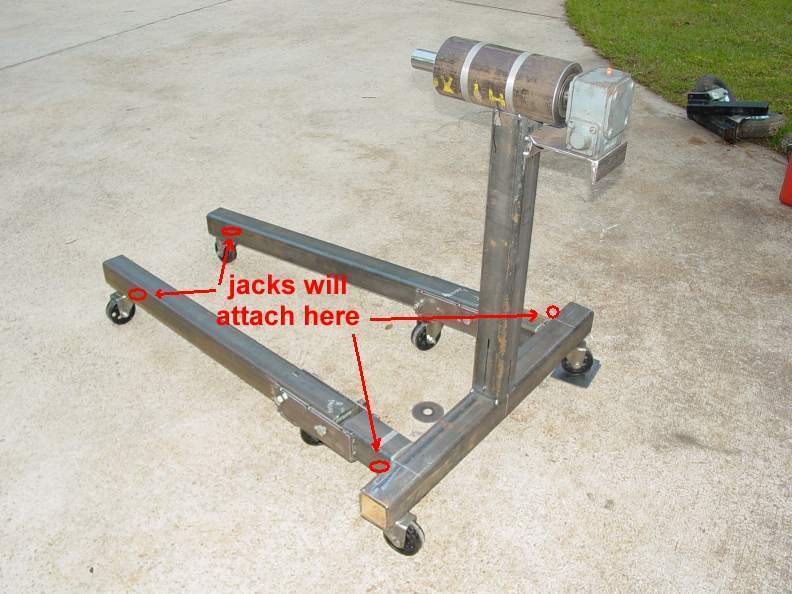
The legs will angle in slightly in order to allow an engine to be bolted up from a cherry picker and they will also hinge and fold upward to conserve floor space when not in use. Three inch Solid steel casters which were saved from a wheel replacement on a set of wheel dollies will be used. While they are non-bearing wheels they will roll well enough for short moves around in the shop. They aren’t locking casters (it’s what I had), but I’d suggest if you're buying casters get at least 4 locking casters. Steel or hard plastic casters will work best and not 'flat spot' from having an engine sitting over them for years/months/weeks. Well, after a short pause for work and chores… I’m back on the stand… got the base fabbed up and tacked together. But, dummy me forgot to take pictures of the individual pieces… so just look at the part I’m discussing and ignore the rest… The base is composed of 9 pieces… the back piece (leg) … two short stubs… two hinge sections and the two legs (and a couple of braces) The back leg is 34 long and the two short stubs are welded at 4” in from each end. The stubs are cut at a 95 degree angle so the legs turn in a little. (remember the 'mount from an engine hoist part ?) They are 26” wide (o.s. to o.s) at the back leg and 20” apart at the far end. This allows you to roll an cherry picker up to the stand and mount the engine directly to the stand.
Here’s a little closer view of the leg stub.
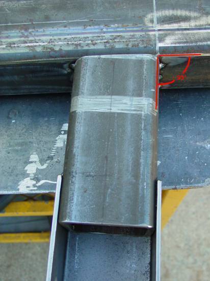
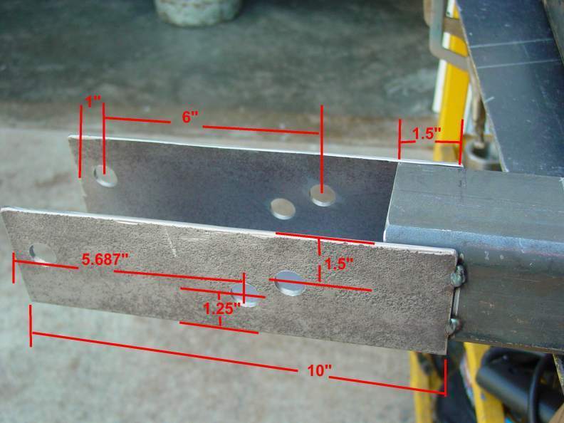
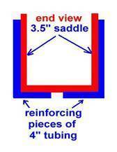
The hinge pieces or saddles SHOULD BE fabbed from 3.5” tubing with a 1/4” wall thickness. Mark and drill the holes for the legs before you cut off the top of the tubing. If you cut the tubing before drilling the pressure of the drilling will make the tubing sides flex and it will make your holes a little off.. The top keeps the tube rigid and allows you to apply pressure when drilling… Also, these holes are more easily drilled with a drill press due to the diameter. You could probably do it with a hand drill, but you’ll be tired and your holes won’t be as accurate. A 5/8” drill is tough to handle by hand…especially when it creates a burr and hangs up. The two leg mount holes are for 5/8” bolts… but I drilled them 11/16” diameter. That’s about a 16th sloppy but makes it easier to insert the bolts… and once the engine load is on them you won’t feel the difference… They are 6” apart… and 1” from the leg end of the hinge. Step drill these holes… I started with a 3/8 bit then the 5/8” last.
The lower hole in the hinge is to lock the legs in an upright storage position… it will take a little finessing when you drill the legs to make for a good fit… see below. You can probably tell that my hinge saddles are NOT 1/4” wall. The only piece of 3.5” tubing I had was 1/8” wall. (again trying to keep with the zero expenditure theme) After looking at the design I could see that this piece was a weak point and might tend to bend with 700-800 #s hanging on the head and a little bouncing around on a rough floor. I took a section of 4” tubing and cut it down to add two external pieces to add to the saddles.. they will cradle the hinge saddle and reinforce it greatly… They were drilled to match the hings saddles and will be welded to it on each side and bottom… a reinforcing saddle for the saddle… If you do have 1/4 " wall tubing... forget you read this.
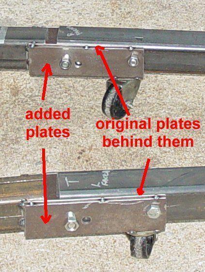
the reinforcing saddle saddle might not be needed…. But won’t hurt… if you can build it…OVERbuild it! Here’s a shot of the hinge point with the reinforcing plates added. This is another of those after the fact pictures !
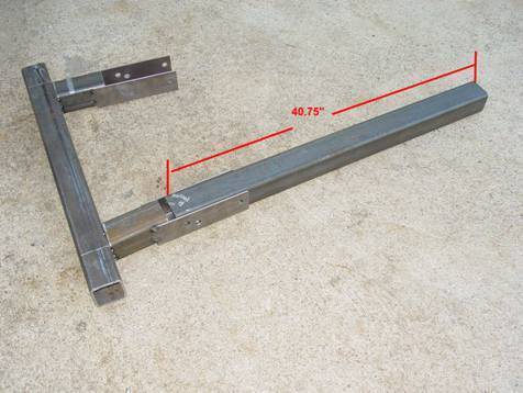
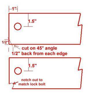
The legs are 40.75” long and the picture below shows how they are cut and drilled.
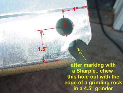
After the leg is cut to length it needs to be drilled for the hinge bolts… the holes should pretty much match the hinge holes (if you want the dang thing to go together properly)… on the hinge end of the leg drill a 11/16” hole 1” back from the end and 1.5” from the top and bottom edges… or centered on the side. Drill a second hole 6” inward from that one and hopefully the holes will match up with the hinge piece. Before the leg can be swung up into the vertical storage position it must be trimmed on the bottom corner to allow it to swing in an arc when raised. Miter the lower corner of the leg at a 45� degree angle approx �” in from the end.
Here it is tacked together
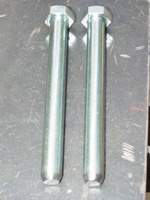
When both legs are mitered and you place the back hinge bolt thru the leg and saddle, the leg should swing up freely to vertical. With it vertical, look thru the lock hole (the lower hole in the hinge and you can see how much to trim the leg for the lock bolt to clear. It’s easy to mark the leg using a Sharpie pen through the hole then remove the leg and trim it. A 4” angle grinder will do this quickly and with a little patience make a nice hole. The rear hinge bolts will always stay in the base so you can use bolt/lock nut combo for them.. The front will be remove for storage position so you can use either bolt/nut or fabricate a 5/8” removable pin with a hairpin clip and washer to hold them in place. You can buy these at tractor supply places or trailer supply stores… or simply take a 5” piece of 5/8” rod… weld a washer on one end as a stop… insert it in the hole and mark the other end for the hairpin remembering to allow room for a washer. Remove it, drill the hairpin hole and you’re done… insert the pin, slap on the washer and insert the hairpin. Or, even something easy like this 5/8” x 8” bolt.. cut off the threads and taper the end… the head will be cross drilled and ‘chained’ to the base so they don’t get lost
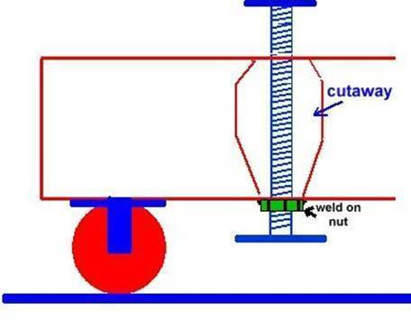
Before attaching the upright and head, it’s a good time to put on your casters. I’ve seen caster mounting plates welded on and then drilled and threaded to bolt on the casters… I can’t ever see removing the casters so I’ll just tack weld mine to the legs. You’ll need 6 casters… 4 for the rear part of the base and two for the front of the legs. If I were buying my casters new I’d buy 4 locking and 2 non locking.. the locking ones would go on each corner and the non locking in the middle. My casters are all non locking… I’ll probably add some screw down legs to hold the stand in place when working on it.. torqueing head bolts requires a stable engine stand.
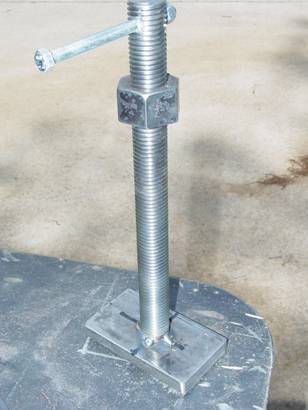
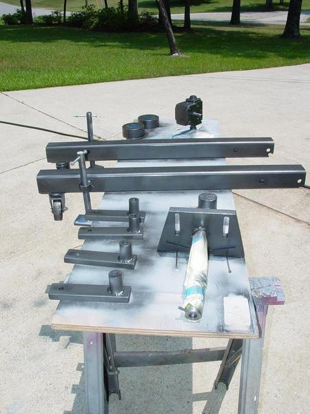
SO… I did build the screw down legs… well I’ve built them… just haven’t tacked them on the legs yet… I took 4 pieces of 1” all-thread and nuts… some 3/8” x 2” flat bar and a little grinding/drilling and welding. Ground a flat on one side of the rod stock and center punched it…drilled it for 5/16” bolt for the handle…wouldn’t hurt to dress the threads with a file to remove the drilling burrs after drilling to make the nut thread on easier … came up with this
The legs will be attached by welding the nut to the frame legs… two on the back leg just outside of the front leg stubs…and one each on the folding front legs on the outside edge just behind the casters.
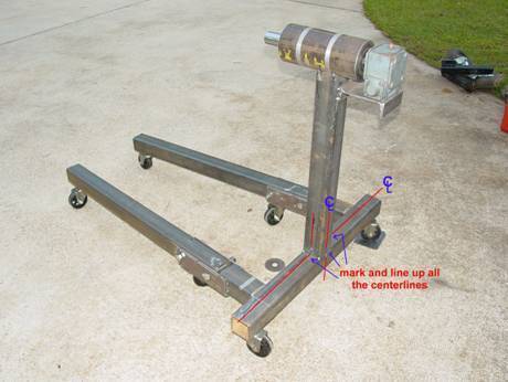
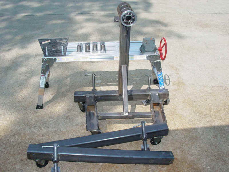
So… back after a few days at the coast… I flipped the frame/base over and tack welded the wheels on… as I said, these aren’t locking wheels but they were free… I can add the feet shown above later… the base is complete and the vertical beam and head are also tacked on now. This thing is getting heavy. The vertical and head probably weight in excess of 50#s… it won’t blow away in the wind… and I don’t have to carry it anywhere either. I’m pleased with it so far. It seems plenty stable. The wide base and legs will distribute the weight evenly and I don’t see a point that will make it off balance… here’s where we are…..
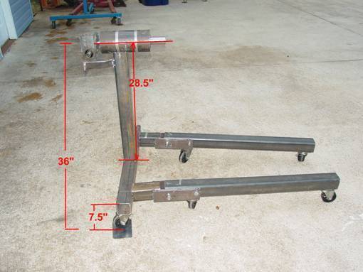
Here again my pictures lag behind my work… this is of course the whole thing… so I’ll tell you about the vertical and head install now. I wanted the engine centerline (shaft centerline) around 36” so I measured from the ground up to the top of the back leg.-- 7.5” I subtracted that from 36 and measuring from the center line of the head down the shaft I made my cut mark at 28.5” and chopped her off. (see above) The placement was simple… mark the center lines of the vertical on both sides and the center of the back leg… line up all the marks… that’s the easy part… holding the vertical beam straight, plumb and centered is a little more difficult when working alone. I used two large welding magnets, one on each side, a building square to keep it plumb left to right and a level to keep it plumb front to back… thank goodness for magnets.. a couple of quick tacks, check the levels and square and then serious tacks to hold it in place.
Now that you have a complete rolling base, it’s probably time to attach the vertical beam and the head. Now that
pieces are in place and tacked …everything is plumb and square.. you can add the
cross brace. I used 1.5”x1.5” tubing for mine. Measure the cross distance between the two hinge plates about
halfway between the hinge bolt holes.. Cut the tubing to fit
(remembering to miter the ends to match the angle of the legs and
tack it into place. Make the tubing flush with the top of the
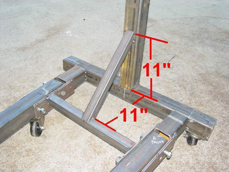
hinge saddles. A vertical brace was added….. It’s approx 11” to the cross
brace from the vertical and 11” up the vertical.
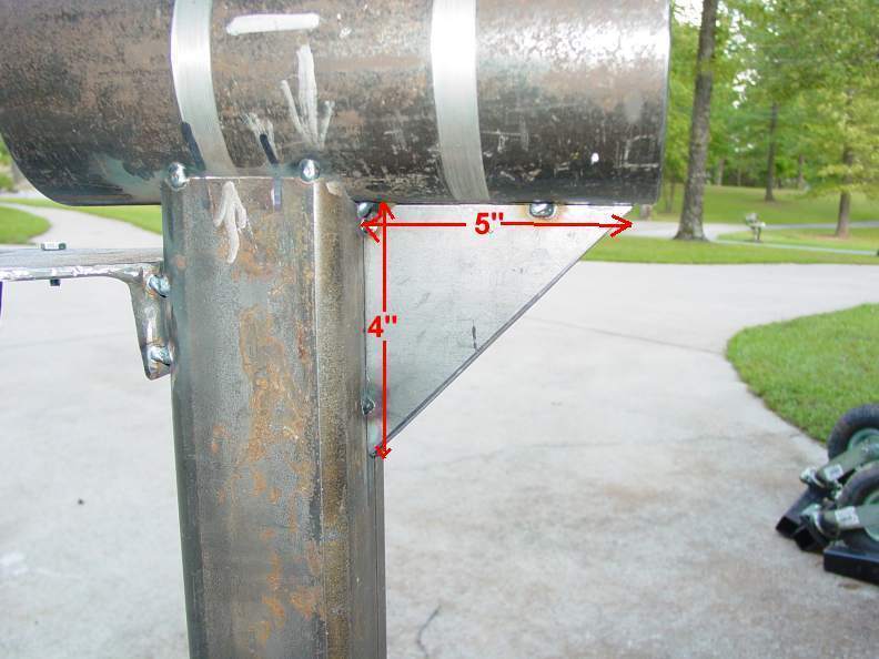
The only pieces missing are the engine mounting plate, the engine connector pieces... the end caps for the tubing and a couple of gusset plates… the end caps aren’t absolutely necessary, but they do dress it up a bit and cut down on ankle cutters. Cut the end caps to match the tubing size (3” x 3”) and weld them on… grind to pretty up. I showed before in an earlier picture a gusset plate I’m adding under the head unit bracing it to the vertical beam. With a 460 cu.in. engine hanging out there on the block mounting plate there will be quite a bit of stress on the head and the welds to the vertical. The gusset plate is just an added safety margin.
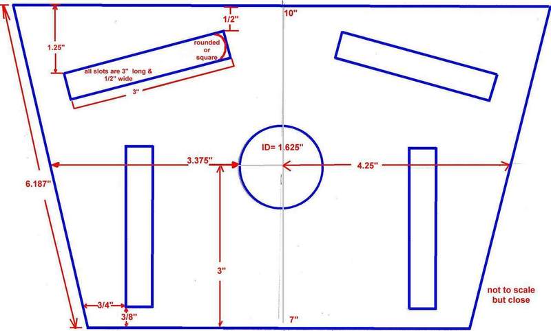
The engine mounting plate was left till last for a reason. I’m having a piece of 3/4” plate plasma cut by a friend with a new CNC plasma table. We’re waiting for the table to get set up. So, the best laid plans... and you know the rest of that tune... The plasma table was put on hold due to budgetary restraints... so we resorted to hand flame cut. The head was cut and it now sitting (hanging) on the shaft awaiting the welder. The head piece was cut from 3/4" plate using a torch. Dimensions are 10" across the top, 7" across the bottom and the sides are 6-3/16". My center hole is 1`-5/8" to match my shaft. Slots are 3" long and 1/2" wide to accomodate up to 1/2" bolts. I'll be using 7/16" bolts to match the rear of a 460 engine. I'm sure the closer you place the center shaft to the actual center of the block (weight wise) but easier it will turn and the more balanced the load will be on the bearings... I had no idea how to calculate that center line without a dressed engine. I only have the block right now...so I'm just guessing. I'm pretty sure I'll be heavy on the top side but hopefully not too much.
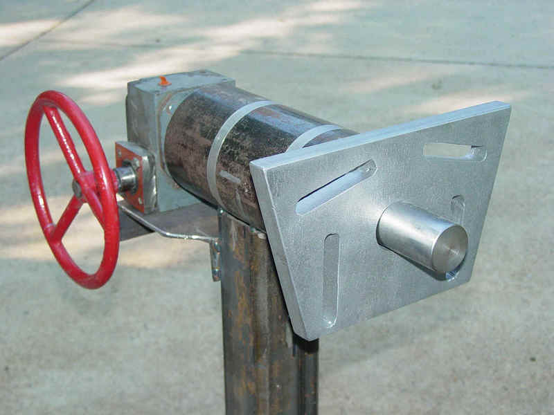
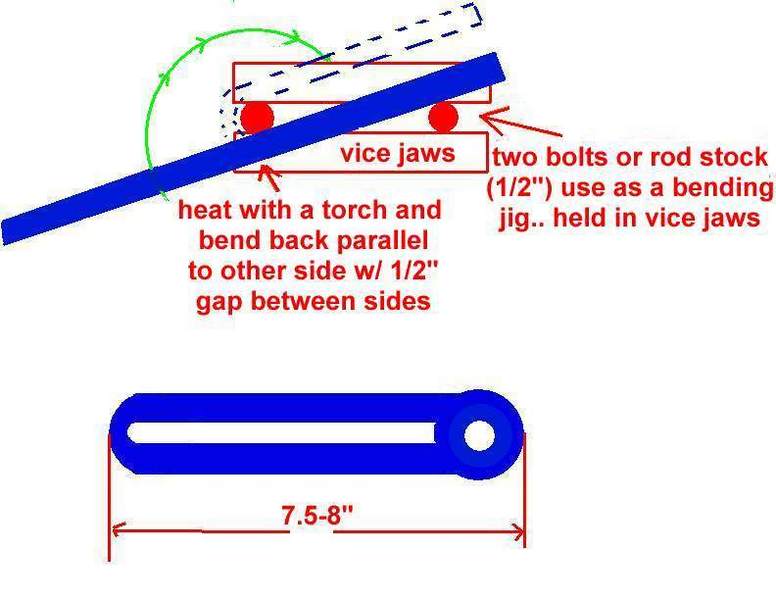
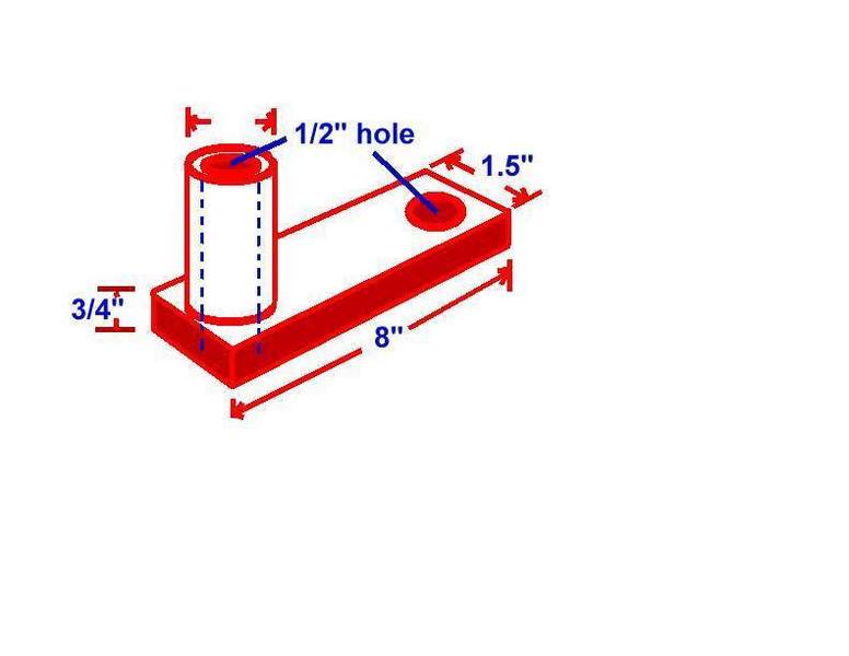
The shaft will have to be trimmed off to the proper length before welding and my Metabo will do that part this afternoon. Everything else is tacked in place and waiting for final welding. pictures to follow. I've attached the 'steering wheel' now... it was a valve actuator drive wheel for a 10" gate valve. Everything turns nice and easy now... the real test will be when the block is hanging off the end. There are a couple of ways to fabricate the connecting arms. The first example below uses flat bar bent into a "U" shape and pipe added to attach to the block and the head piece. 2" x 1/4" would be a good choice, as would 1-1/2" by 3/8". Just make it substantial A bending jib can be made from two bolts held in a vice. The flat bar is heated and bent around the pivot bolt as shown. Do this with ample heat and do it slowly so you get a nice "U" shape on the bent end. Schedule 160 pipe o.d. is .840 (about 7/8") and wall thickness of .188 (abt 3/16") ...or something with a nice thick wall for the sleeves.... You could always drill out some square or hex stock. (see pics below) While the 'looped' flat bar will give you infinite adjustment for attaching engine blocks...you have the length of the looped section and the 3" adjustment in the engine head plate....the flat bar on the right will have 3" of adjustment and should fit nearly any v-8 block that you might encounter. This was my choice. 3/4" x 2" flat bar 8" long with the Sch 160 pipe for the sleeves, welded to the flat bar. The bar is step drilled on each end to 'easy fit' a 1/2" bolt... (17/32" hole).
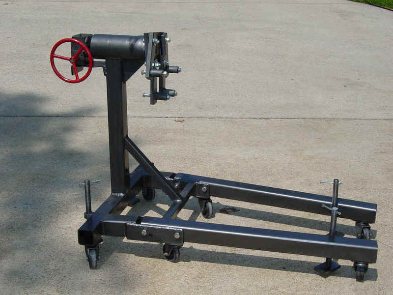
So, now the final welding is complete and everything is ready for paint.
A shot of primer on everything and set it in the sun to bake... followed by several coats of rustoleum metallic charcoal rattle can paint.
and here it is complete
it's about a complete as I can make it... unless I add a hook to hold the pins that hold the legs in place when vertical. I could just drill a hole in the base section and stick them in there. Total cost came in around 35 bucks I think... $15 for the gear box.. $15 for paint and $5 bucks for hardware I didn't have. I think I have much more than a $35 dollar engine stand now. I'll know more soon when the 460 is back hanging on it... and no, you can't borrow it.
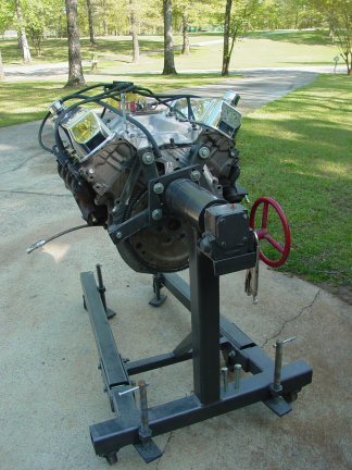
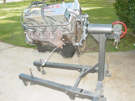
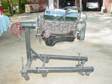
Sometime later..... big>finally got the engine back...put it in the truck for some measurements and now it had to come back out to work the firewall and make it pretty... So, I snatched it out and mounted it on the stand... here's some pics... I had to modify the top arms... they were too long... so I cut them down and redrilled them... The engine hangs nicely on the stand... part of the sag in these pics to due to a sloped driveway. There is some caused by the 'slop' in the fit of the fold up legs. The third cause is basically 700 #s hanging on the end of a 2" bar ! It actually works too well, you can grab the valve covers and turn it by hand... and if you use the wheel on the gearbox it literally turns with one finger... even your little finger. I put a pair of vice grips to hold it in place.... I need to come up with a braking mechanism... it's just too smooth and easy now !
Boilerplate denial of liability
statement… i.e. the fine print This device is something I came up with to
prevent me from spending too many dollars on a commercial patented device, it
is not patented, engineered or even perfect… it is what it is, a home made
contraption. I’m sure there are alternatives to this design some even
better/cheaper/easier, I just didn’t think of them or warrant them necessary... there
are several similar units on the internet waiting behind Google for you to
see/copy/build…(just like I did) This work was done by me and for me or by
friends who were nice enough to help me out. I only ask that if you reproduce it give me
credit for it and if you make money from it… give me my percentage. Since I have no way of knowing your
level of competence, welding or cutting skills, mechanical ability or estimated
intelligence, there are no guaranties or warranties either verbal, written or implied with
this article. Along with this article I am giving you absolutely free of
charge…that’s right ! FREE !!...the liability, total
and complete liability for the use or misuse of this contraption will be yours and yours
alone. It belongs to you with that in mind… I
am in no way responsible for any damage, injury or embarrassment you may suffer from the
use of this homemade device. If it doesn’t look like something you’d
be comfortable using… don’t build/use it. If
you’re not intelligent enough to make that decision about your comfort level…
ask a family member or friend.. but here’s a hint… if you have to ask
someone… don’t build it ! Pictures were made at different stages of
construction and all assemblies in pictures may not be complete in each shot. I.e.. a
picture showing ‘some parts’ only means that it was not finished, but I’ve
tried to make the idea complete to the best of my ability. If you have questions or see
mistakes or problems, let me know by e-mail and I’ll make the corrections if
possible.. Use these ideas at your own risk. Modify
them at your discretion and to suit your purpose. Your mileage may vary, batteries not
included, much assembly required... wait one hour after building to enter the water,
additional charges may apply. not all applicants will qualify for advertised A.P.R., for
ages 10 to adult…side effects are comparable to placebos. Do not take drugs when
building or operating machinery. JUST SAY NO. Copyright . 2011 John Niolon, All International Rights Reserved. This document may not be copied or published without prior written consent of the author- jniolon@att.net |
|||||||||