 |
 |
| THEIRS | MINE |
PLANS FOR A PRESS TYPE METAL BENDER |
|
|
| THEIRS | MINE |
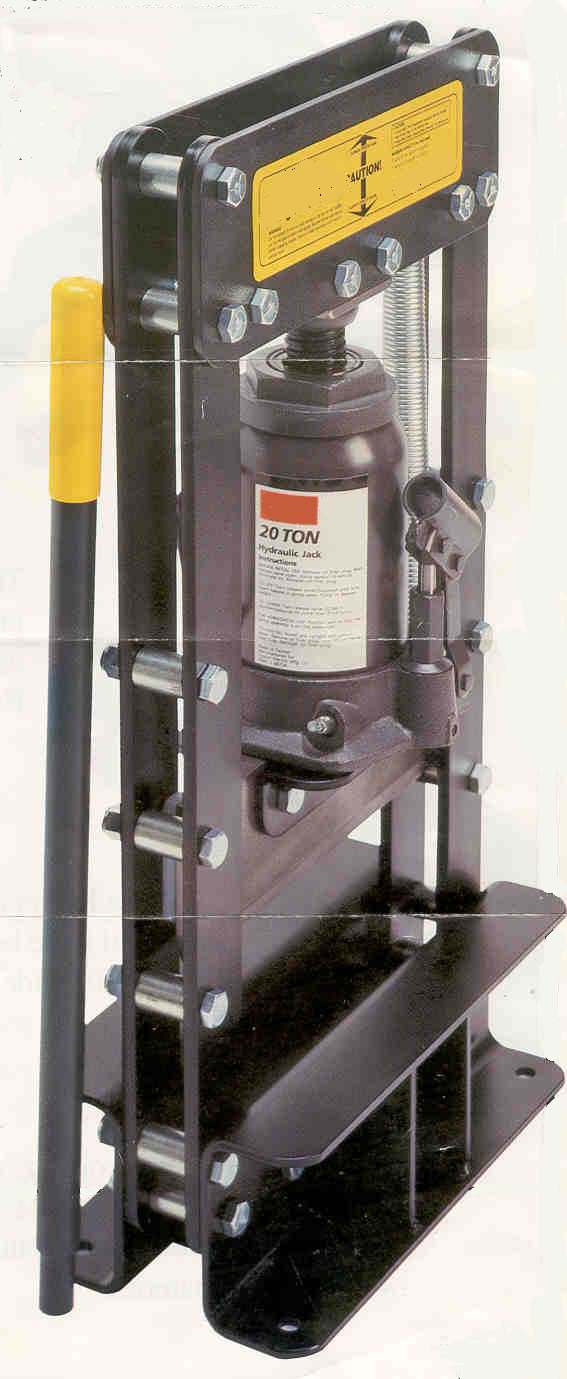
Ever since I first saw the ad for the "Universal Metal Bending Press Brake" I wanted one. But, the 400 dollar price was a little steep for a tool that I would only use occasionally. Still, it's heavy, it's thick, it bends stuff... thick stuff. No more hammers and vices and torches to fabricate a facsimile of a bracket I want. So I took a picture about this size and started scaling dimensions. The overall height and width were given on the flyer so I had a starting point. With my little calipers and dividers and a scale, I proportioned everything out to what I've built.. It's taller than the original and from the onset I had a reason for that, but I can't remember it now. I have to say that this project started two or three years ago and between work and other tasks and gathering parts it's been put on the back burner several times to simmer or to just get cold and wait. |
| With the exception of the press bar itself, all materials are made from common steel. The base is 8" channel, the uprights are 2" bar stock and the top plate is 3/8" plate. The jack base is 3/8" angle. The press bar is a material called "Astroloy", a steel superalloy that is extremely hard, made for high pressure, high heat applications. This is what we had, but you need something with a hardened surface to prevent mushrooming and spalling of the press bar itself. |
| I guess the best way to describe all this is to start with individual parts with pictures and drawings... then put it all together... First.. all dimensions are accurate but the drawings are not to scale.. all holes (except eyebolt holes) are drilled for 1/2" grade 8 bolts |
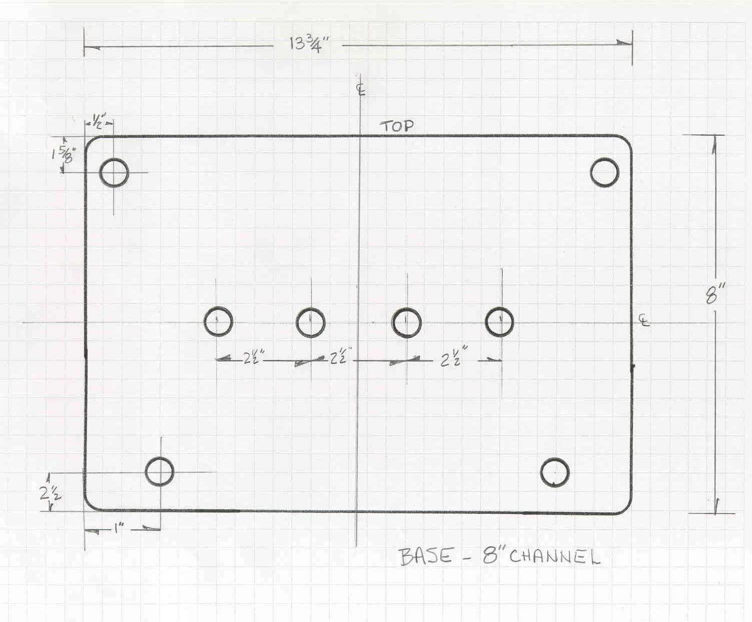
| BASE PIECES The base is made from 8" channel. It is 13-3/4" long. The four holes on the centerline are equally spaced. They hold spacers and bolts that keep the base from spreading under load. The exact dimensions are not critical, and holes should be evenly distributed inside uprights. Note the upright holes at top and bottom are on a different centerline. of course you will need two of these ! Before assembly, take a 4" grinder and radius the upper inside edge of the base pieces. This will give the stock you're bending a little rounded edge to roll off instead of a sharp 90ş angle to bend over. Not much, just a little. |
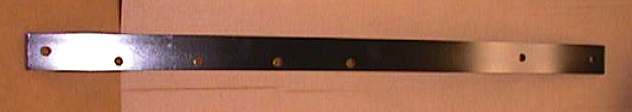
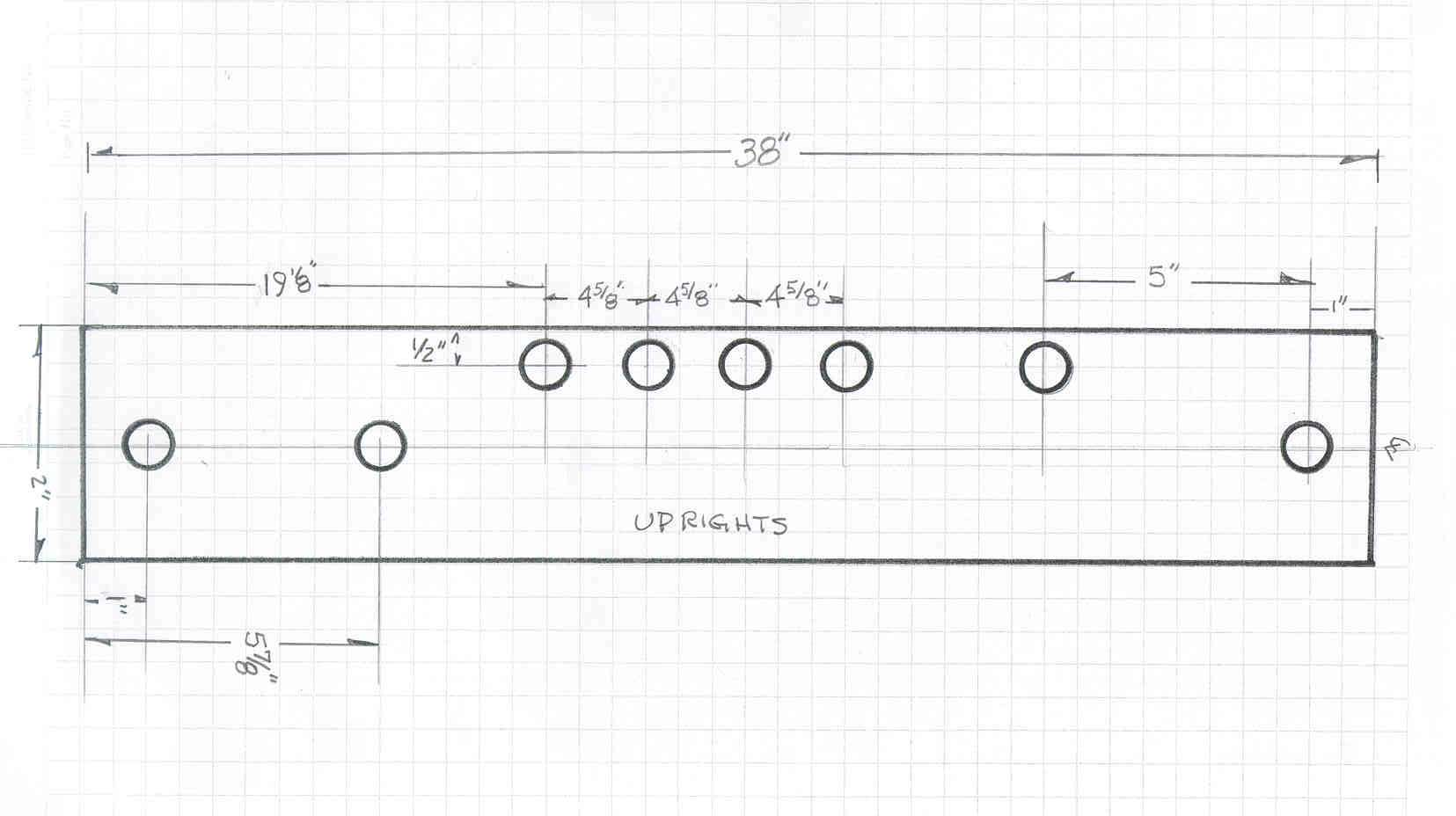
| UPRIGHT
BARS The uprights are made from 2" x 3/8" bar stock. The three holes in the center of the bar (on 1/2" center line) are also not critical. They are there hold to uprights in position and prevent colapse of the sides. Space them equally between the top plate and the base plate. You need 3 of these |
|
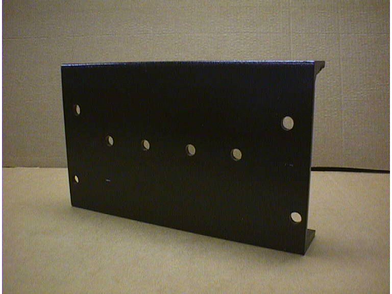
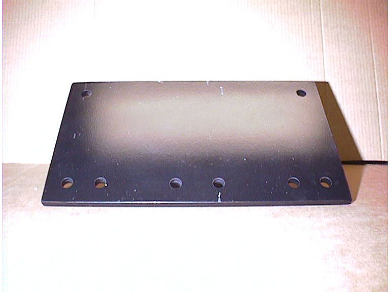
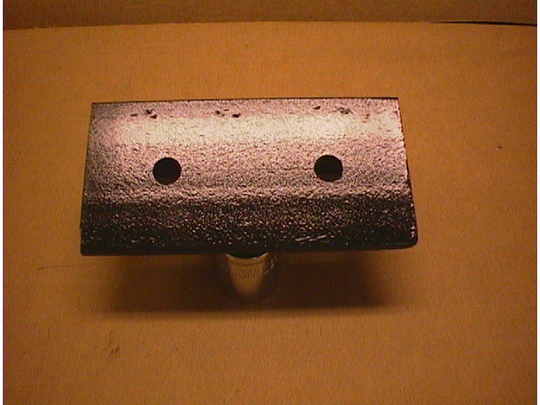
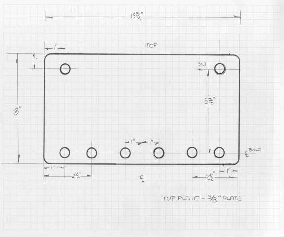
| TOP
PLATE The top plates are made from 3/8" plate and all hole dimensions are to be drilled as noted. The two holes in the center at the bottom of the plate hold the press block. |
 |
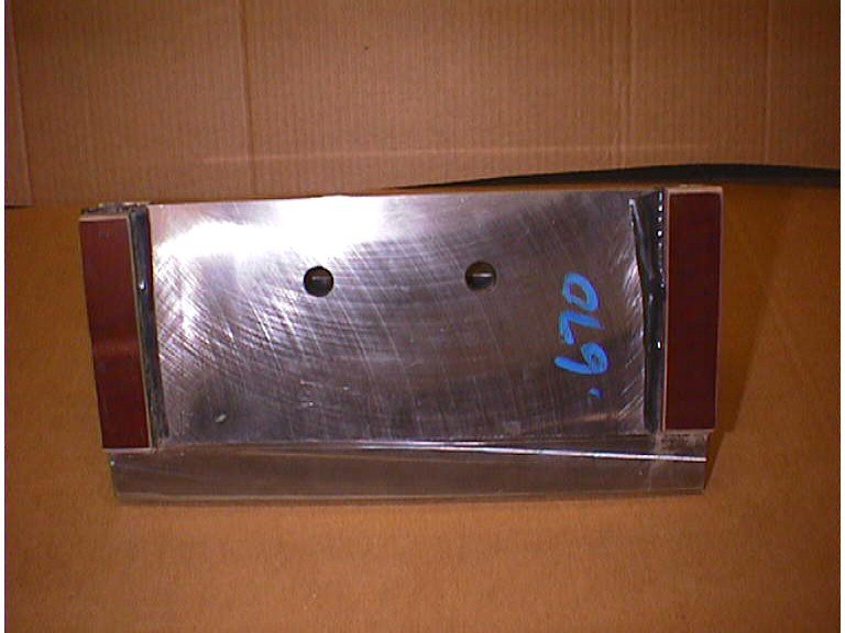
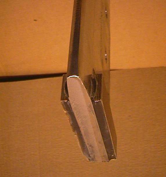
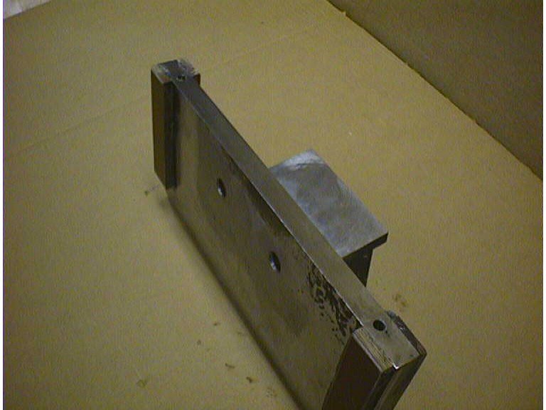
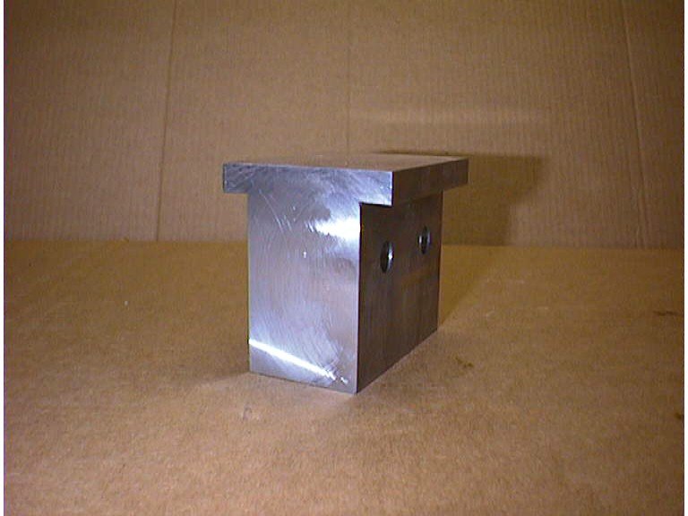
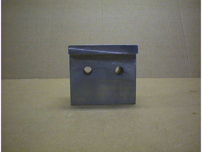
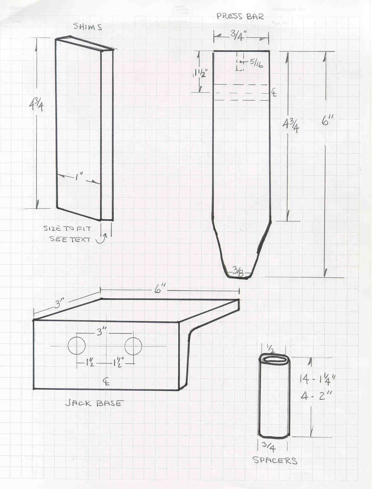
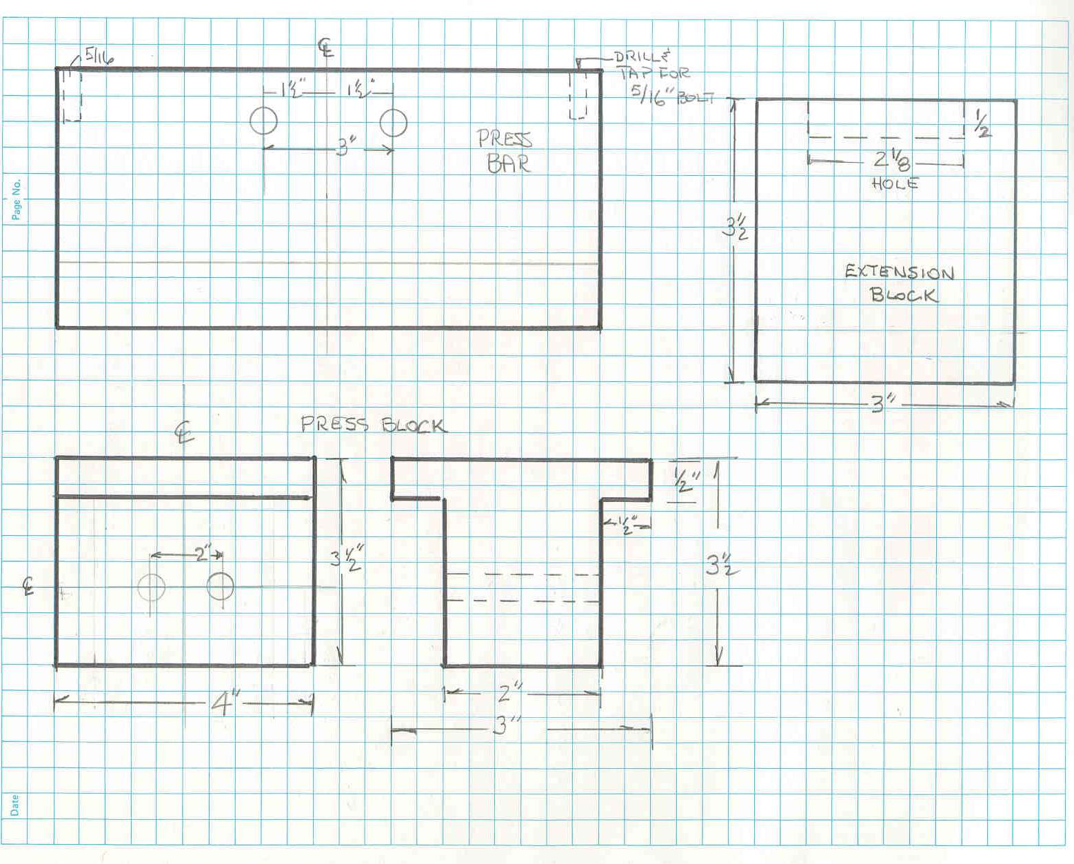
| PRESS BAR The press bar, as stated above should be made of a hardened material to prevent it being damaged when applying pressure. We had a piece of "Astroloy" about the correct size and used that... but any material with a hardness greater than the stock you are bending will probably work fine. This will not be a 'production' type machine and occasional use will not damage it. This material as well as any other hardened material will be much more difficult to machine and to drill and tap. Looking at the attached drawings you can see that the stock is 3/4 " thick and tapers down to 3/8" at the bending edge.. The taper starts at approximately 1-1/4" up the plate. The edges should be champhered to give a smoother bend and easier operation. One the top edge, tap two holes for the spring eyebolts. I used 5/16 eyebolts...use what you have, but keep in mind that the press bar, jackbase and jack will weight around 50 pounds and your eyebolts need to be able to lift that weight. Drill the bar at the top to bolt on the jack base. The jack base angles should fit flush with the top of the press bar so all three pieces are bearing the pressure of the jack. The picture below shows the press bar with the shims already glued into place. the lower picture shows the edge view and the taper |
 |
 |
 |
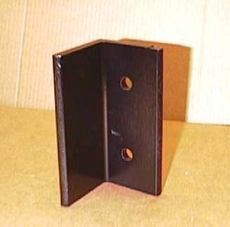
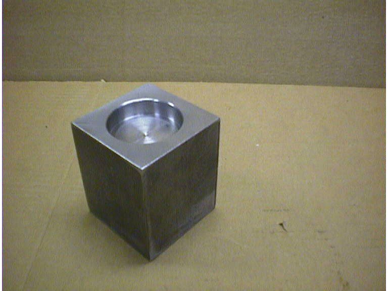
| PRESS BLOCK The press block was machined from a piece of 4" key stock to the dimensions shown. You could probably make due with welding one up from three pieces of 1/2" plate. Two legs to slide up into the top plate and the face piece that the jack presses against. You could possible put 20 tons on this piece...so build it accordingly..I like the solid bar stock myself. |
 |
| JACK BASE The Jack Bases are made from 3" x 3/8" angle - 6" long. They should be slightly larger than the base of your jack... size yours accordingly.
|
  |
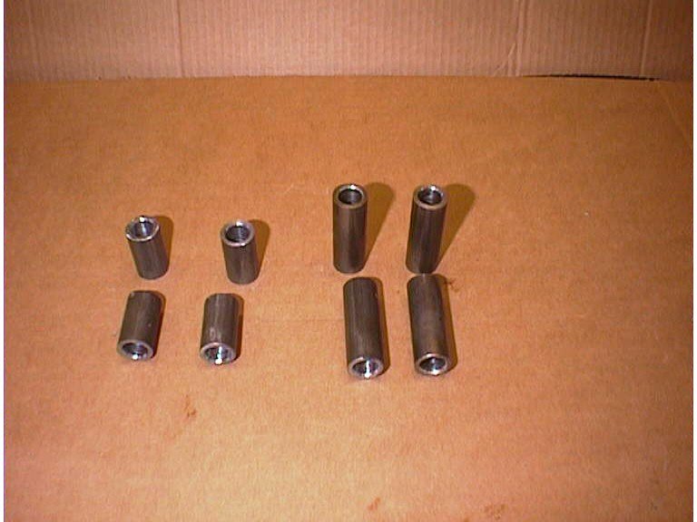
| SPACERS Spacers are used to hold the two halves of the press apart. They were made from 3/4" o.d. tubing and drilled (reamed) for a 1/2" bolt to pass thru them. You will need two sizes. First you will need 14 - 1-1/4" that fit between the uprights, and 4 - 2" spacers that fit between the base channels. Here again diameter isn't a big deal but the lengths should be very close and all of each type should be exactly the same. |
 |
| JACK The jack I used was a Northern Hydraulics 20 ton bottle jack. there are many on the market with similar ratings. The jack was about 10" tall with 6" of cylinder lift and about 3" of screw extension. |
 |
| SHIMS You will need to add shims on each side of the press bar to make it fit reasonably well between the uprights.. you don't want a tight fit... give yourself about 1/32" free play to allow for easy movement. I made my shims out of Micarta blocks 4-1/2" long - 1" wide and roughly 3/16" thick... You need to measure the distance between the uprights, subtract the press bar thickness and divide whats left by 2 then subtract 1/32. I used standard Epoxy to bond them onto the press bar, after roughing the press bar with course sandpaper. You can see these shims on the pictures of the press bar above. |
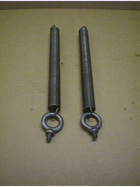
| SPRINGS You will need two springs to return the jack and press bar after your bend is made. They will attach with eye-bolts to the press bar in the two holes drilled in the edge. They attach to the top plate with one of the cross bolts. You need to size your springs for the weight of your jack/jack base/ press bar. I used springs with a 1" diameter, 10" in length and they had 7" of deflection at a 25# load. This is strickly a CWAG formula here and your mileage may vary. I'd get an idea of the total weight and then search the McMaster / Carr catalog for the spring I needed. |
 |
| MISC A few miscellaneous notes. All the bolts are 1/2" Grade 8 with Nyloc Nuts. We did all the fabricating and fitting with standard nuts and the final assembly with the Nylocs. Grade 5's would probably handle it... but it's your 20 tons pressing on your metal with your body standing close to it... I've personally never wanted to see a Grade 5 bolt fly across my garage like a bullet, but that's just me. I am fortunate to have a machinist buddy who did all my machine work...we swap machine work for computer work... I always get the best end of the deal :-). |
| SKETCHES Below are some rudimentary sketches of what we built. As I said above, the sketches are NOT to scale but the dimensions are true. I'm not a draftsman (and I never wanted to be) This is the results of high school drafting class 38 years ago... At least it's not on the back of an envelope... |
 |
 |
 |
 |
 |
| PUTTING IT TOGETHER |
| I put a coat of primer and rattle can paint on everything before I
assembled it. Then almost immediately after I started I removed the paint from the
inside of the uprights where the shims ride. The fit was too tight and the paint
tended to gum things up. A little lacquer thinner made this an easy job. Begin by assembling the frame. This is accomplished best with a helper. There are a lot of things to hold in place. I layed the base on its side and one of the top plates at the correct distance away. Then layed two uprights on this...then the spacers... then the other base and top plate pieces. A drift helps line up all the pieces to install the bolts. I'd recommend snugging everything up then standing the unit upright. Check for square with a carpenters, try or combo square and tighten the four corners, with regular nuts. Then add the other bolts and the lock nuts. Finally replace the nuts on the four corners with lock nuts.
|
 |
| Before putting the press bar in, lubricate the shims and the inside of the
uprights with some slick stuff. I used white grease, but use what you have that's
slippery. Insert the press bar by turning it at angle and then sliding it down
gently. I had already screwed in the eye bolts and attached the springs before
inserting the press bar. Next thing to do is attach the springs to the bolts at the
top. Since the press bar is heavy and you only have two hands, I'd recommend
raising the pushbar to the top, and sliding a piece of 1x2 thru the frame above two of the
top cross bolts to support it. Then, you'll have two hands to hold the spring in
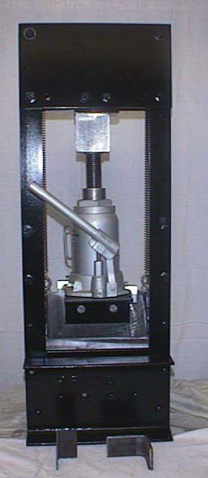
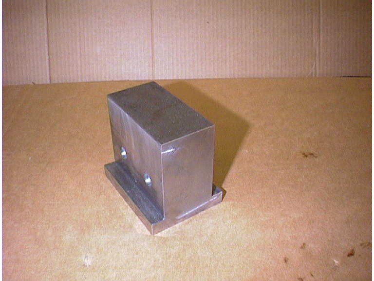
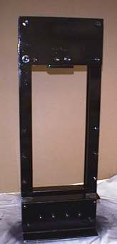
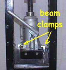
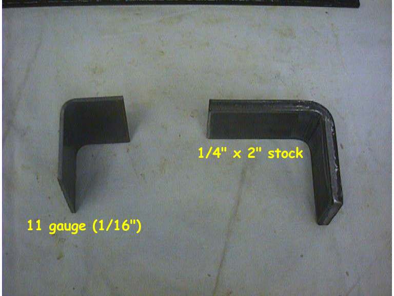
place and stick the bolt thru it. Attach the jack base to the anvil and place your jack on the base. This is a little precarious at this point. I used a couple of beam clamps that electricians use to attach the jack to the base. It might never fall out.. but I like my toes, cute and round.. not flat and bloody. Next I inserted the jack extension and it was done. The picture below shows the completed unit and the one below that shows a sample of the bends I tested. The smaller is some 11 gauge material... the other is a piece of 1/4" plate 23" wide and 7" long
|
 |
| A heavier pull bar will be cut. The jack handle doesn't give you enough leverage. It's not all pretty like the original with nice radiused corners and powder coating.... but it serves my purpose well.. hope yours does also. |
|
 |
| Copyright © 2002 John Niolon, All International Rights Reserved. This document may not be copied or published without prior written consent of the author - jniolon@wans.net This work was done by me and for me. I only ask that if you reproduce it give me credit for it and if you make money from it… give me my percentage. Since I have no way of knowing your level of competence, welding or cutting skills or mechanical ability….there are no guaranties or warranties either verbal, written or implied with this article. Pictures were made at different stages of construction and all parts in pictures may not be complete in each shot. but I’ve tried to make the plans or drawings complete to the best of my ability. If you have questions or see mistakes or problems, let me know by e-mail and I’ll make the corrections if possible.. Use these ideas at your own risk. Modify them at your discretion and to suit your purpose. Your mileage may vary…. batteries not included…. much assembly required…. wait one hour after building to enter the water….additional charges may apply…. not all applicants will qualify for advertised A.P.R.….for ages 10 to adult….( dang I’m almost not old enough to use it !) side effects are comparable to placebos…. Do not take drugs when building or operating this machinery John Niolon |