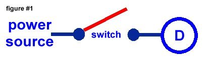
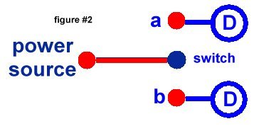
One of the things we have to contend with when restoring or rodding these old trucks is the wiring (or lack thereof). How many of us have looked under the hood or dash board to find a mess that can only be compared to a backlash on an old casting reel. Bare conductors, frayed and missing sections of insulation, Wire nut connections and I’ve even seen a patch made with stranded clothesline wire wrapped with vinyl tape. In addition to the disrepair, most of the older models were 6 volt systems and even when new were marginal performers. As the years added their toll to the wires, insulation, connectors and fuse blocks the performance degraded exponentially. There are many aftermarket solutions to the problem that include everything you need to rewire your trucks except the beer, the colorful language and the fast pain relievers like Tylenol and Advil. Headaches are included in the kit. While some of us find the wiring simple and straightforward, there are many who regard anything electrical as akin to alchemy and the black arts performed by wizards and sorcerers.. The new kits come with pre labeled wiring and cover most every device you can add onto our vehicles but sometimes leave a little to the imagination when it comes to the actual hookup of devices and especially to high amperage parts like sound systems, horns and auxiliary lighting. But, they are sized properly for operating relays that can handle the switching of these big boys of the electrical group. The contacts of the relay can transfer the high current from the source (the battery) to the device without burning out or burning up. These contacts are operated by a magnetic field that is produced by a coil. When the coil is energized the relay contacts move from one point to another, and either turn on a device or turn it off. There are variations to that theme, but basically that’s it. In the diagrams below I’ll show the basic parts of a relay and how they work together to do the job. Figure #1&2 shows the basic diagram for a switch. Figure #1 shows a single pole single throw (SPST) switch similar to what you use every day to turn on a light bulb. |
|
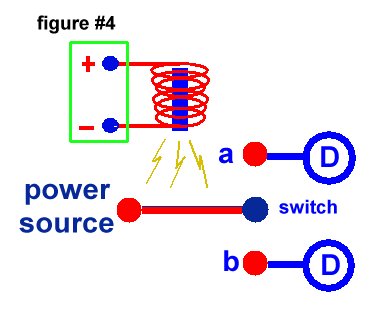
| Normally the switch
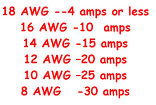
is activated by flipping a lever or pressing a button or in some instances, turning a key. It is a single pole double throw switch (SPDT) and switches the power from the source to one of two contacts… if the switch is moved to contact “a” then power flows to it’s device and of course if the switch is moved to contact “b” it’s device is powered.. The variations on this configuration as well and are nearly endless… more contacts can be added as well as switch arms but the all basically work this way.. Simple, right ???? The power or current that a switch can handle is only limited by the wire size and the size of the contact points in the switch. Of course, the larger the wire and contacts… the more power or current the switch can handle. There are tables everywhere on the net that will tell you what size wire you need to handle what amperage (current) based on the length of the wire. Switches are rated the same way and are labeled with their maximum use on their cases. Here’s a general guideline you can use for automotive wiring Wire lengths are generally less than 25’ and don’t offer that much voltage drop at that length |
|
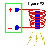
| You all remember the 3rd grade science experiment in magnetism. You took a big nail and wrapped a whole gob of insulated wire around it then connected the wire to a battery… and walah !!! the nail turned into a magnet. You learned that the battery voltage created a magnetic field around the nail and coil of wire… an electromagnet. You spent the afternoon picking up gem clips and magnetizing your buddy’s watch. Relays use an electromagnet to close and open the switch or switches they control. Look at figure #3 this is the coil we just talked about. Now look at figure # 4 and see how it is incorporated with a switch.. when the coil is energized the magnetic arm of the switch moves between the contacts and you have a relay. |
|
| In most situations
the arm is spring loaded and is not touching a contact (in a SPST relay) or in
contact with one of the contacts when the coil is not energized. When the coil is
energized it will pull the arm to the other contact. Again there are
variations…..there are different configurations of relays referred to as
‘normally open’ and ‘normally closed’ which refer to the
position of the arm when the coil is not energized. Normally open the
arm will be away from the contact (in a SPST relay) or not connected to the device
contact in a SPDT relay. Normally closed relays are just the
opposite and actually open the circuit (remove the power) when the relay is activated.
For our purpose here we will deal with ‘normally open’ relays.
Later on I’ll give you some links to more relay information. There are
literally dozens of configurations and relay circuits that can allow you to do most
anything you can think of… turning on a light, changing direction of d.c. motors,
actuating alarms, making windows work up and down, give your neighbor next door a little
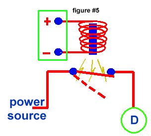
jolt when his t.v is too loud…. well most anything, anyway. Note: for our discussion we’re assuming that the relays we are using are in automobile applications with a direct current (battery) power source… coils are dc devices only. But, relays can be used in a.c applications also. The only requirement is that the coil voltage must be converted to dc. A simple diode added in series with the coil voltage will convert the a.c. to d.c. and the coil will work properly. Som in our simplistic example.... look at Figure #5. When the coil is not energized the arm is not touching the contact (red dotted line) when power is applied to the coil the arm is pulled magnetically to the contact completing the circuit from the power source to the device “D”. That’s all there is to it. |
|
| Ok, so now if the
coil stays energized the device will always be on and run till the power source is removed
or exhausted in the case of a battery source. That’s probably not practical… we
need a way to turn the coil on and off. Now start thinking in terms of your truck…
The power source (for both the relay and the device) has to be the battery, right ?? You
have positive wiring and negative… but the negative is the ground in the truck or the
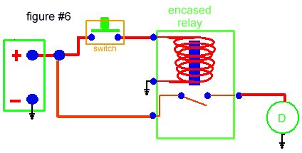
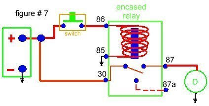
chassis and frame … so half your wiring is already in place isn’t it ??? In our truck situation the circuit would look like figure #6 below… we’ve added a switch between the battery and the coil allowing us to activate the relay when we choose. When the switch is pressed the coil circuit is closed… the arm on the switch is closed completing its circuit and the device is turned on. This switch can also be put in the 'ground' leg of the coil circuit where it would complete the path to ground and energize the coil... either way will work correctly |
|
| Notice again
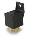
in figure #6 that I now show the relay as ‘enclosed’ these high power devices
are usually enclosed in a plastic case about 1” square with a convenient mounting tab
at one end. Most aftermarket automotive relays are rated at 20, 30,40 or higher amperages. |
|
| The device itself
might be a 50 amp device but the only wiring that must carry that load is from the battery
to the relay and from the relay to the device… the control wiring (coil circuit and
switch) can be small since the coil itself will need less than ? amp to actuate. And, when
the relay is mounted close to the device you cut down on the amount of heavy wiring that
is needed. An example would be headlights… without a relay a heavy wire would have to
be run from the battery connection point thru the firewall to a switch that could handle
the amperage.. then from the switch back thru the firewall down the fender and to each
headlight. But, as stated before, with a relay all the wire running from the relay to the
switch and back can be light guage wire. In today’s vehicles, lots of circuits are operated by relays… cooling fans, head lights, heater fans, radios, door locks, wipers,etc. And, with an endless variety of relay options and configurations you can turn on or off devices, turn on with timed delays, turn them on(or off) at certain temperatures warn you when things aren’t right (door ajar). They are very useful tools. Trying to run headlights on # 14 wire will accomplish two things…. Dim headlights and dangerous circuits which can lead to a cab full of smoke or a fire. Relays in these high amperage circuits protect your truck and give the circuit the power it needs to perform properly. Now… two more things… #1 this little black box has terminals on the bottom that you attach your wiring to with quick connect crimp on terminals. And, the terminals are numbered… not logically like you’d think. I think the guy that came up with the numbering used last months lottery numbers. The standard numbers for most relays are 30,85,86, 87 (and sometimes) 87A Here’s the hookup… 30 – the power lead from the battery goes here (for the high amp device) 85 - this is the ground side of the coil… wire this to a chassis ground 86 - this is the power lead to actuate the relay coil (from the switch) 87 - this is the hi amp output to the device 87A – is for the second contact in a SPDT relay (when switching between two sets of contacts) |
|
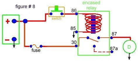
| #2 I did not show any
protection for the circuit at all (to keep is simple). Normally you should put a fuse
holder and fuse in the line between the power source and terminal 30. In this way, if
either the device you're powering or the relay fail, the circuit is protected. If you
prefer to wear suspenders AND a belt you can add another fuse between terminal 87 and the
load. This would offer you double protection. The '87' fuse would protect the circuit if
the device shorts out and the '30' fuse protects you if either the device OR the relay
fail (this advice comes from someone more knowledgable than me in electronics (thanks
Chuck). BUT in any case fuse the circuit, this gives you over current protection and
prevents the circuit from releasing all it’s smoke. (not a good thing) Figure 8 below
shows the fuse in the device line between the battery and the relay… . The important
thing is to have it in there in case there is a short circuit in the wiring or device. The
fuse will blow and save the circuit and you from a embarrassing situation. It
wouldn’t be cool to pull up at the drive-in with a cab full of smoke and you emerging
smelling like burnt insulation |
|
| One or two other
items you should consider. These suggestions were made by a fellow member of FTE and a vehicle
wiring, technically trained guru who maintains a fleet of emergency vehicles...
thanks CBEAV
|
| #1 Quality.
Don't buy the cheapest you can find. Relays aren't that expensive to begin with. You
should buy a name brand unit from suppliers with a good reputation like Waytek
(waytekwire.com) or Digikey (http://www.digikey.com ). There are several behind google.
The same goes for fuses ... stay away from Harbor Freight and other import stuff. Use Buss
or Littlefuse. #2 Alternate Sources... Another source of good quality relays is your local salvage yeard. OEM automotive relays are usually high quality and you can get a handful for cheap. I'd look for the ones that have been out of the weather... i.e. hood still covering fuse block..etc. #3 Electronic equipment... If you are doing circuits for auto components it's wise to use "protective" relays if there are sensitive electronic equipment in the circuit. When a relay 'breaks contact' a spike voltage is created from the magnetic field of the coil that can damage sensitive components. These relays have a diode or resistor across them to prevent that. Lots of info behind Google on these and they are readily available. Now this should have de-mystified the whole booger-bear of relays. They are very simple devices and are one of the most useful tools in the electrical department of your truck. There are lots of good resources on the net if you want to investigate relays further…. Two excellent sites are “The Install Doctor” who offers a pdf file with literally dozens of relay examples http://www.installdr.com/TechDocs/999404.pdf. And The 12 Volt page who not only gives relay info but alsio basic 12 volt dc circuits many of them are vehicle specific… http://www.the12volt.com learn all of this and YOU will be the relay guru that everyone comes to for help. |
|
|
| Mandatory
disclaimer verbage This information was done by me and for sharing amound FTE users. I only ask that if you reproduce it give me credit for it and if you make money from it? give me my percentage. Since I have no way of knowing your level of competence,wiring, welding or cutting skills or mechanical ability?.there are no guaranties or warranties either verbal, written or implied with this article. Pictures were made at different stages of construction and all parts in pictures may not be complete in each shot, but I’ve tried to make the plans or drawings complete to the best of my ability. If you have questions or see mistakes or problems, let me know by e-mail and I’ll make the corrections if possible.. Use these ideas at your own risk. Modify them at your discretion and to suit your purpose. Your mileage may vary. batteries not included. much assembly required. Wait one hour after building to enter the water, additional charges may apply. not all applicants will qualify for advertised A.P.R.. for ages 10 to adult. Side effects are comparable to placebos. Do not take drugs when building or operating machinery…just say no ! All International Rights Reserved. This document may not be copied or published without prior written consent of the author. John Niolon 3700 Virginia Drive Hueytown, Ala. 35023 jniolon@att.net |