Installing a Fairlane
Fiberglass Front Clip
On A
'53 F-100

by John Niolon


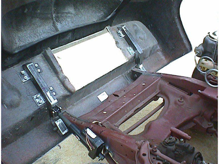
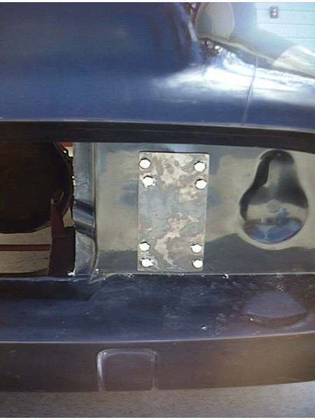
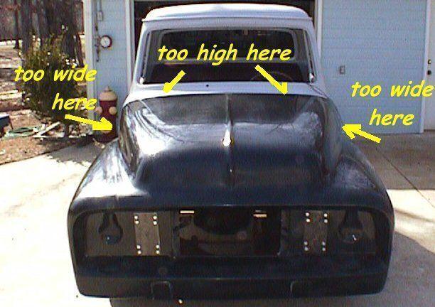
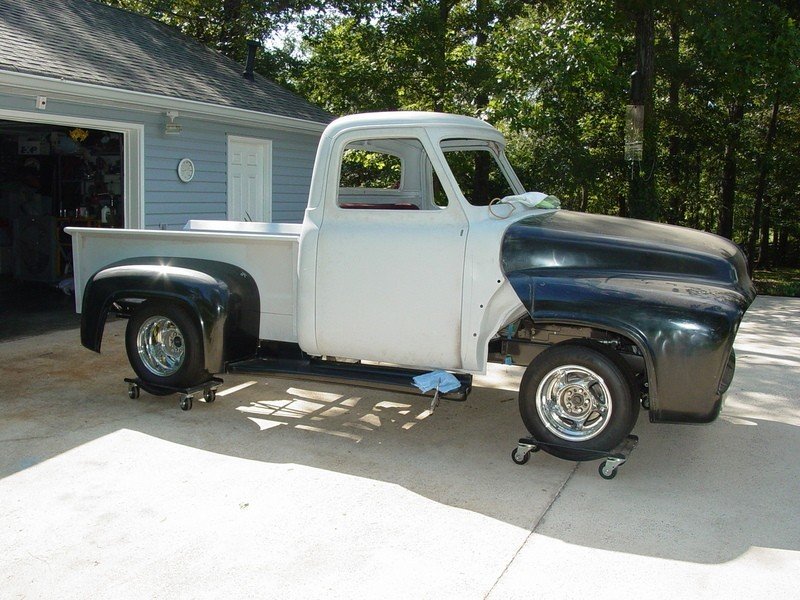
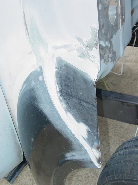
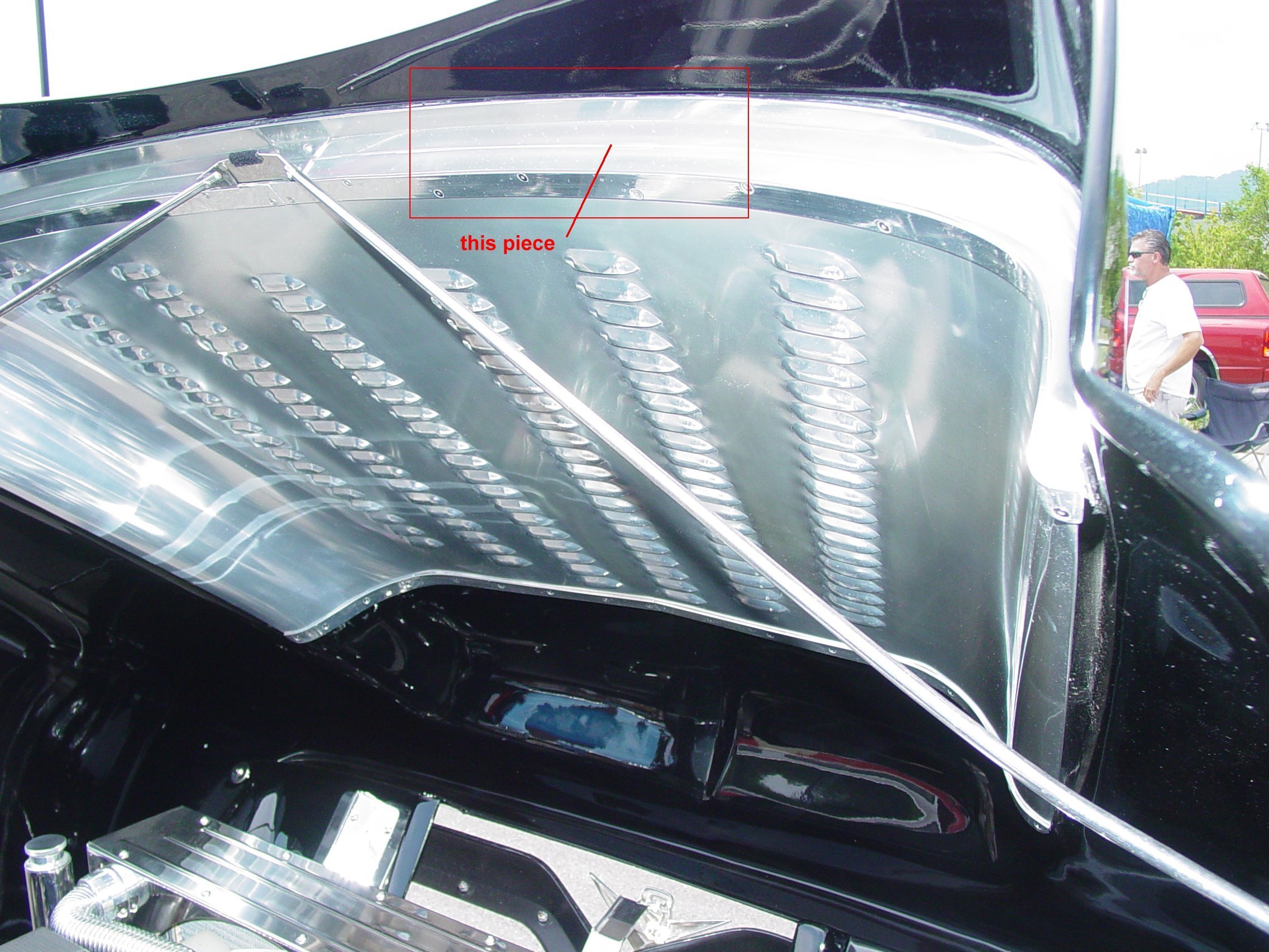
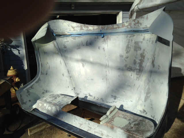
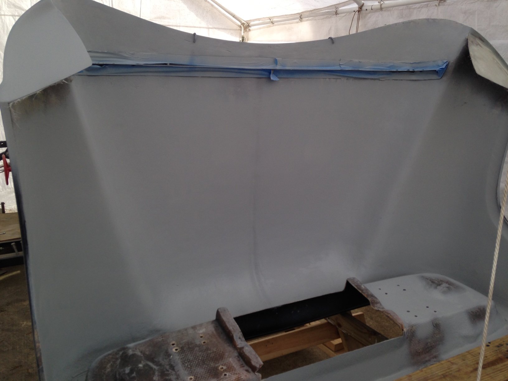
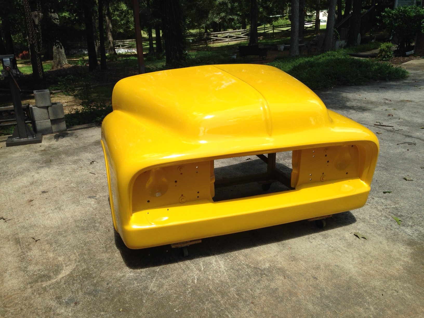
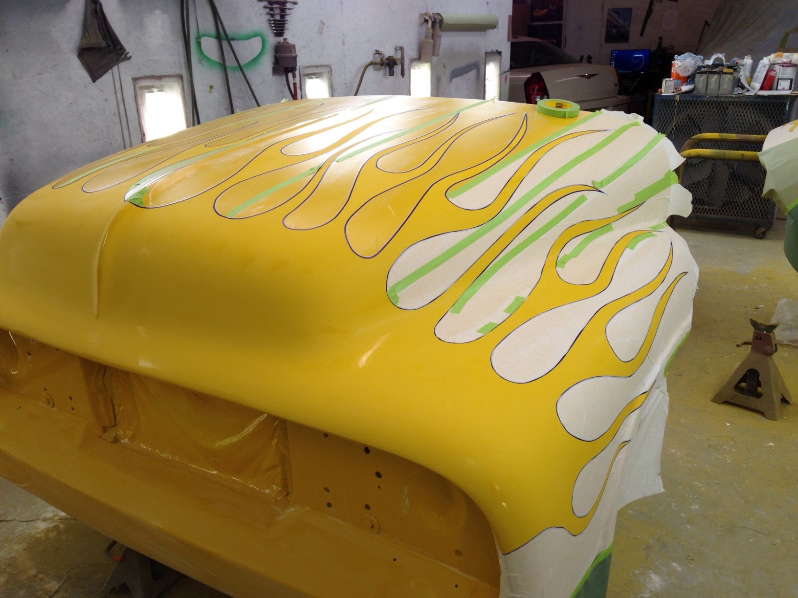
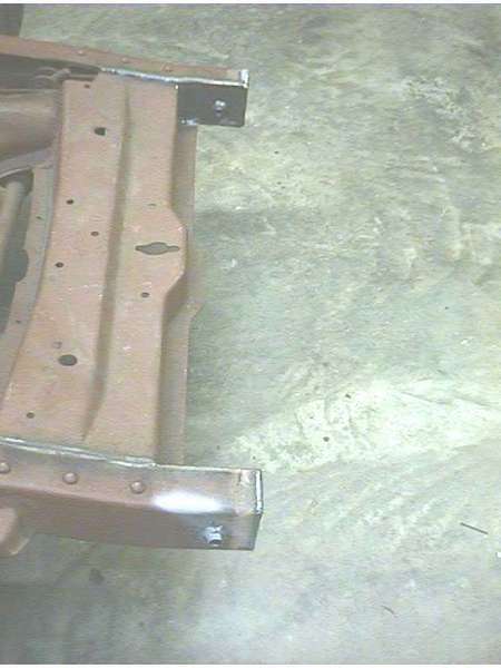
I have this recurring dream… the local cruise-in is tonight and I’ve spent the day washing and drying and rubbing on my cherry ’53. It’s a cool spring evening and I’ve been working and waiting all winter to get the truck on the highway. (Here’s where the dream gets good) We have a great ride across town, cruising just under the posted limit, windows down and good tunes playing. As we turn into the drive-in we drop to an idle (little curtain climbers running everywhere). As we idle through the lot, the healthy lope of the cam and the sound of the flowmasters turning a head or two, we spot a good place to park. Protected from the door dingers and under the lights that will give the paint that little sparkle. We roll just past the spot and back in deftly… pull the brake and flip the switch. Relay clicks, actuator starts to turn and the front end slowly lifts to show off the well detailed 460. Shiny stuff a gleamin’ and all the painted parts scrubbed clean. Folks start to walk over……

What ??? you’ve had that dream too ???…. who hasn’t !!

Well that’s the dream…here’s the reality. At this point in time the truck is nearly half way finished. The Fairlane Co. front flip unit is sitting in the garage with the lower parts of the fenders cut off. The truck is in another garage, cab on frame, bare block in frame, bed up in the rafters waiting on me to finish the brake lines and cables…a pile of 1" and 2" tubing waiting for the elves to convert it to a tilt hinge unit for the hood………We’re a long way from the dream… but we’re working on it.

Ever since I saw my first full flip front end, I knew that it was what I wanted. I studied every one I saw. I had taken lots of pictures. Both metal and glass units I’d seen at car shows, the F-100 gatherings at Pigeon forge, and cruise-ins. I’ve asked questions on the internet and read magazine articles (too few of those around) I’ve laid under most of the ones I’ve seen and memorized what I liked and disliked.

There are a number of decisions you have to make before you start cutting and welding. Like, bumper or no bumper, tilt and slide or tilt only, electric, hydraulic or manual lift. And, if you choose hydraulic, pump size, location, hose routing. You also need to consider latching the hood down and appropriate stops, padding, limit switches, cylinder stroke lengths, wiring, plumbing..etc… The Fairlane Co has been making quality flip units for years and there are others that make them also. I looked at several and in my opinion, the Fairlane is the best constructed and has the best finish quality. I will add though, their support on mounting and tilting was pretty much limited to "we sell the hinges also". Several phone calls and a couple of face to faces at Pigeon forge gleaned very little information, even after I laid out the cash on the hood, for the hood. Disclaimer… I have no connection with Fairlane or their associates… I just like their hood.

The unit I bought came with knockouts for the frame rails. If you decide to run bumpers, they come right out.. If you’re running smooth front, you can fill them in easily. I plan to use the front end without a bumper so the front frame horns needed to be trimmed back some. A little measuring and cyphering came up with seven inches. A plasma cutter made a quick buzz around them and they clinked to the ground.. very little grinding dressed them up nicely. The front end unit was carefully set up on the truck, the rear lip resting on the cowl and the front end sitting on a low stool with shims to get it at the right level. As you might guess this is a two person job.. it’s just way more than one person can get his hands around, so find a helper. My helper was Dave Phillips, master fabricator and builder of much sought after drag cars in our area. I’ve never seen a project that he couldn’t do and the finished product was a thing of beauty. The man don’t make no junk.

Anyway, we walked and looked and rubbed seams and joints and talked. The hood in general looked fine but the fit at the cowl was going to be a problem. The thickness of the material (3/8") had the hood sitting too high above the cowl and there wasn’t even any padding under it yet. And, the hood flared out a little too much on each side of the cab. While we discussed the problem and the solutions we came to the decision that the fabricating of the tilt unit shouldn’t be deterred by these problems…. That’s ‘glass’ work and we’re here to bend steel and weld stuff and such. More on that problem later…back to the task at hand.

Dave had never done this but with the pictures and several drawings we took what we liked from the pictures and came up with a plan that made us happy. As I said before…give the man an idea and he can build it.

We started by boxing the front frame rails from the cross member forward and capped the ends. We then cross drilled the box and welded in a 3" section of 5/8" o.d. tubing. We had reamed out the tubing with a ½" drill until a ½" bolt moved easily through the tube.

framehorn3.JPG (89168 bytes)                                      framehorn.JPG (103929 bytes)                                      frontfull.JPG (45171 bytes)
 

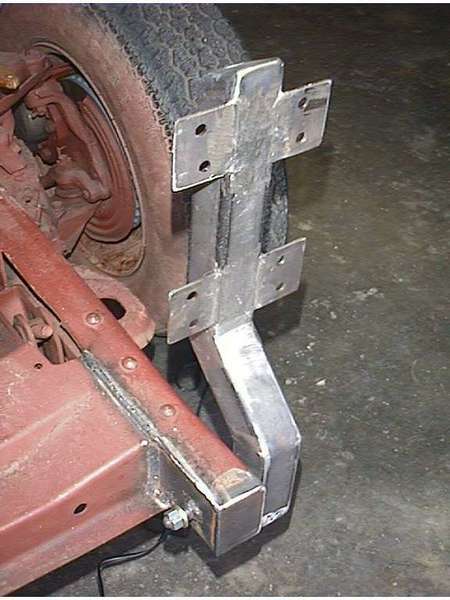
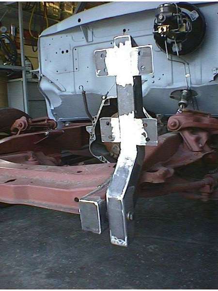
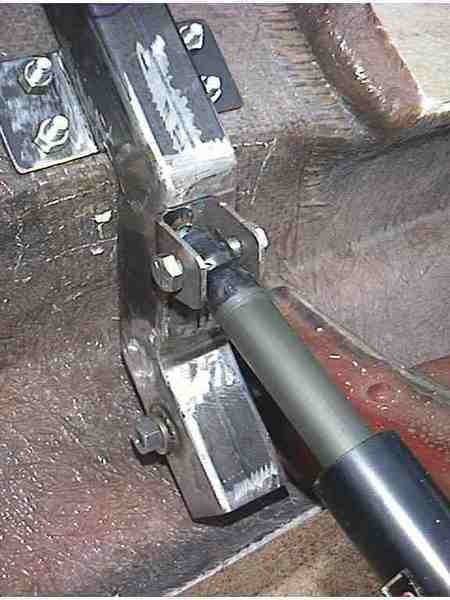
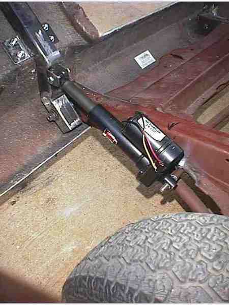
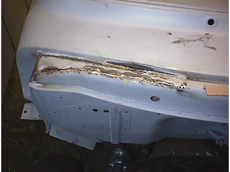
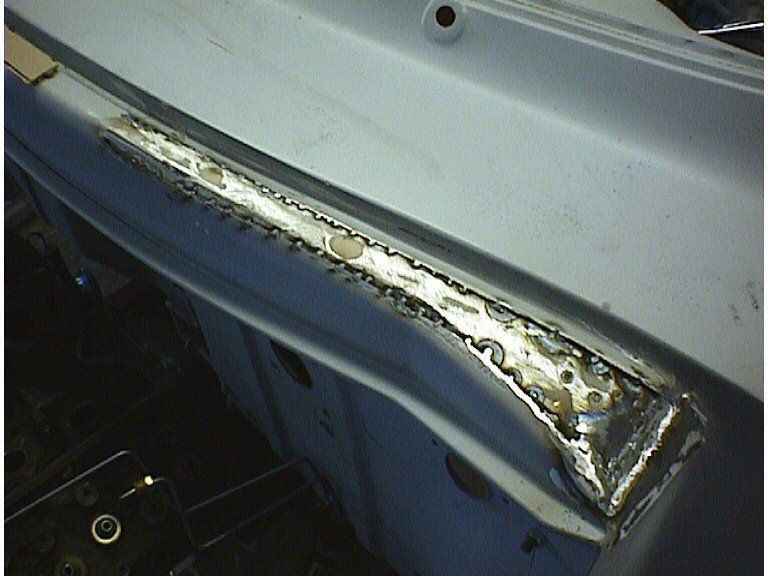
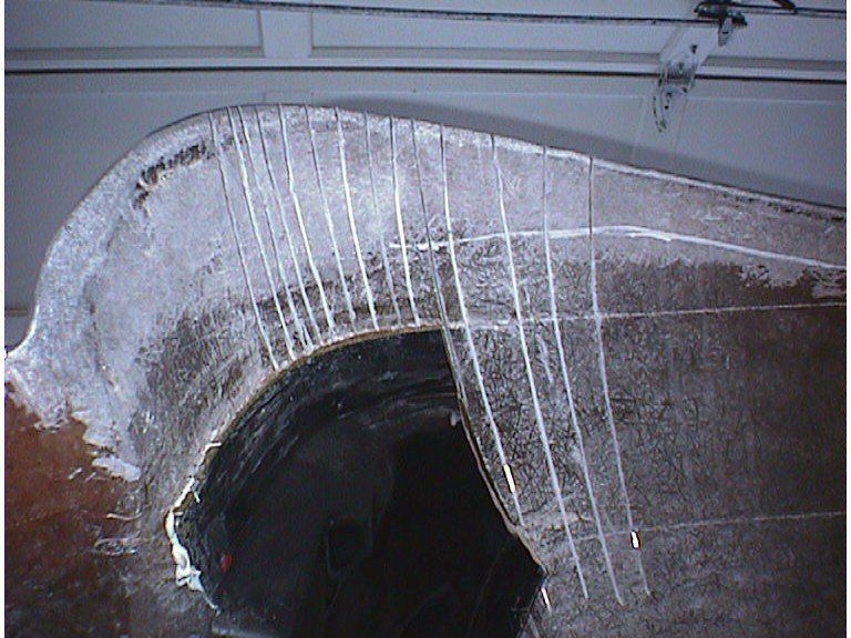
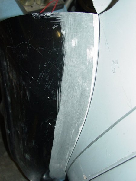
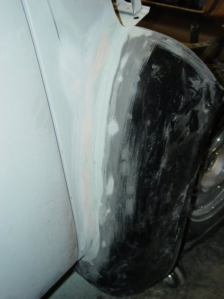
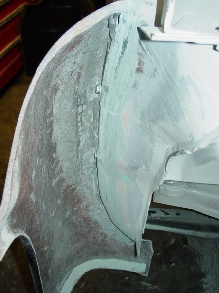
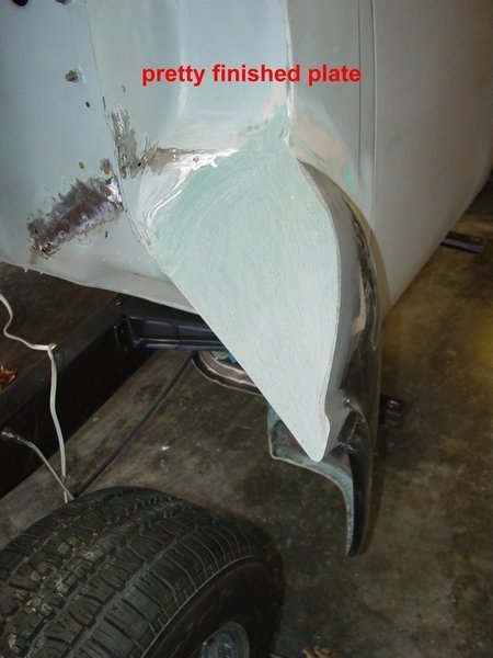
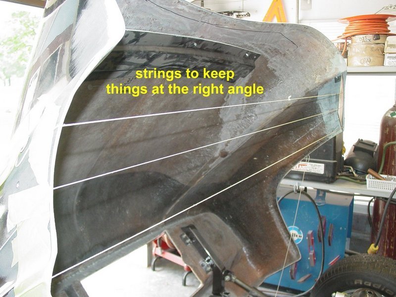
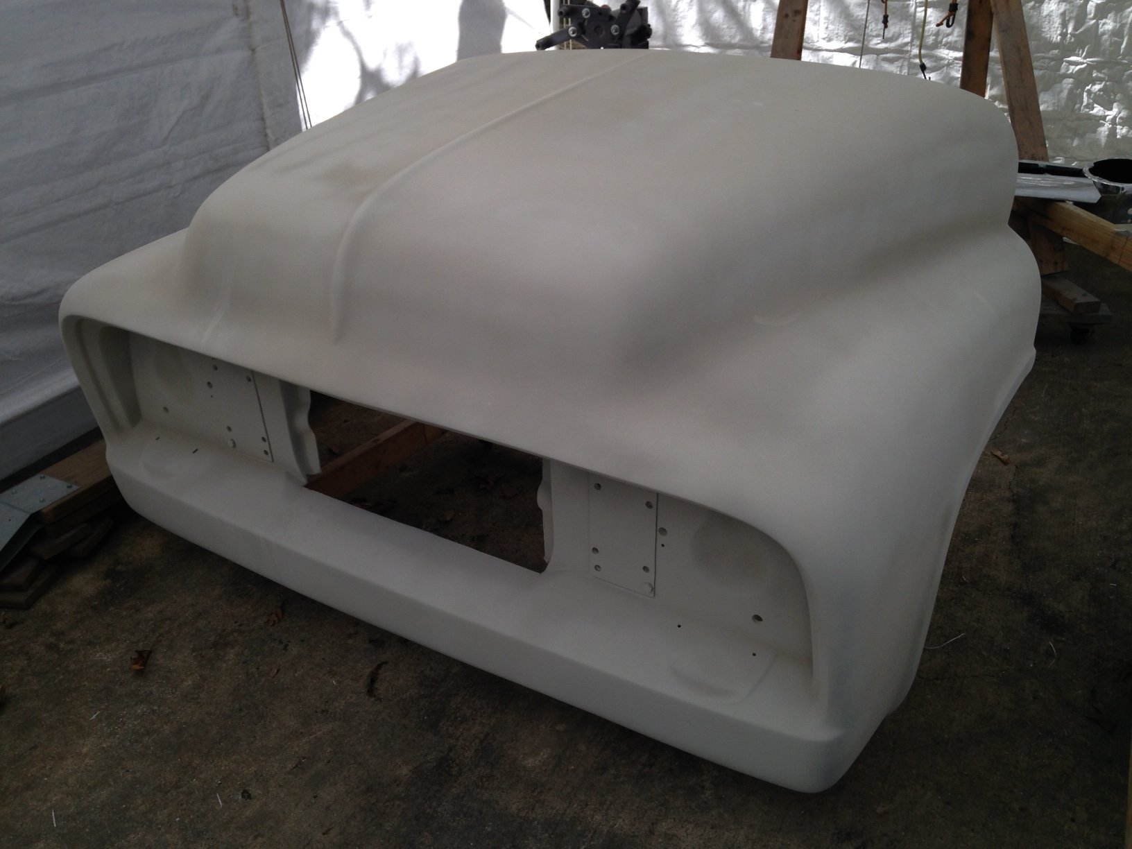
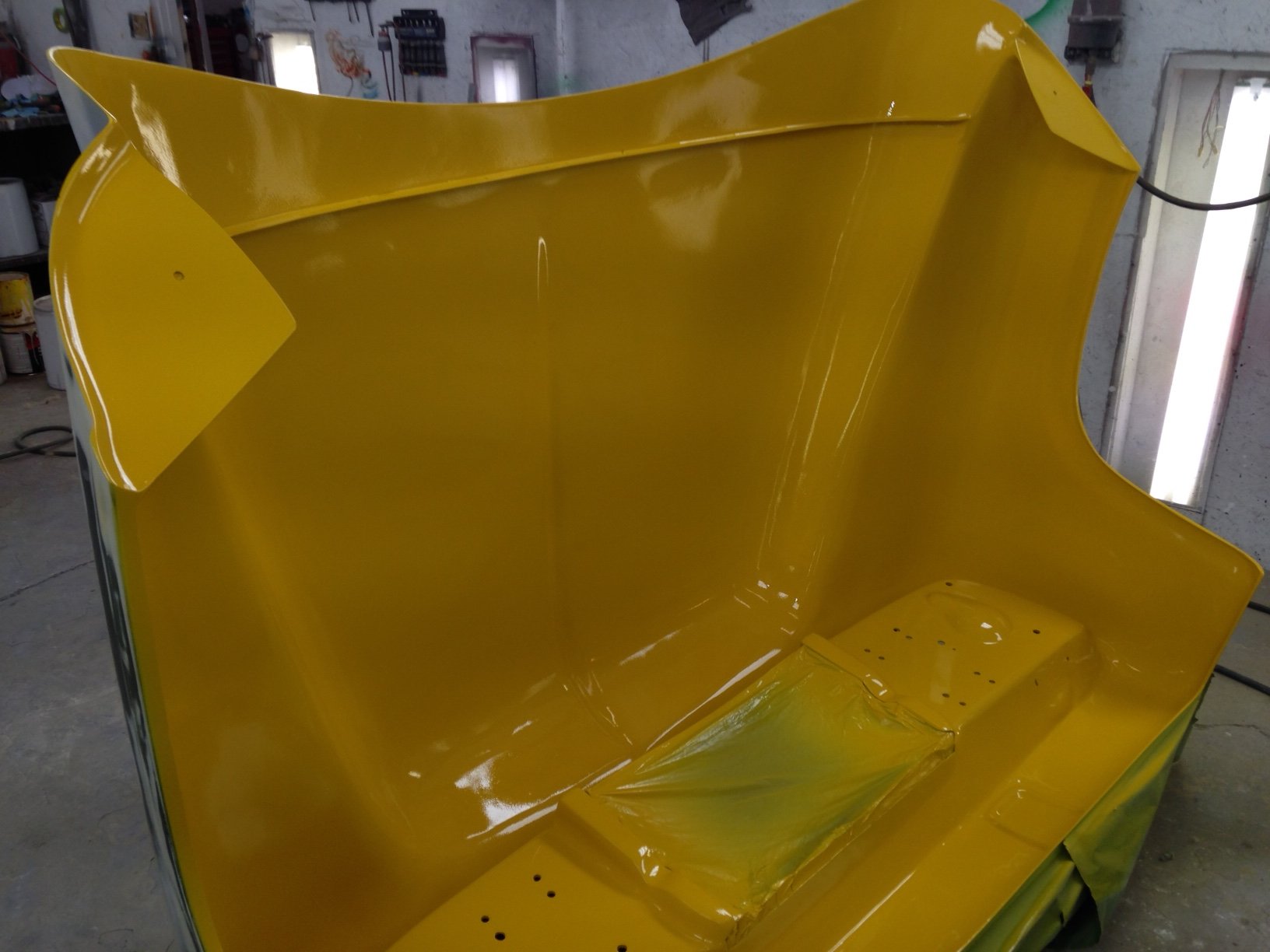
This being done, we moved onto the actual tilt mechanism. There are several ways to approach this. First it should be said that unless you plan to slide the unit forward enough to clear the cab, the corners or the lower halves of the fenders will have to be cut off and attached permanently to the cab.

There are mechanisms on the market that will allow you to slide the unit forward and then tilt up, but they aren’t cheap. I’ve seen a couple that use heavy duty drawer slides for the forward move, but they both seemed kinda cheesy. If it slides and tilts it’s got to be smooth, quiet and easy, without a lot or wobbling and rocking. I’ve heard of other plans using screw motor actuators and stuff but never saw them so I can’t give a good opinion on those. So, if you decide to slide.. you have another set of hurdles to jump before you tilt.

If you decide as I did, to tilt only, you only need to decide on where to make the cut in the fender. I like the cut high in the fender and roughly on a line with the body seam in the cowl (see pictures). But the lower cut at the bottom of the cowl is clean looking also… The upper cut needs more body work to finish it properly, the opening between the fender and the cowl should be filled and finished. The lower cut requires much less work … attaching the cut away section to the cab and bodywork only on the edge of the hood piece. Your choice to make.

While the fiberglass in the air deflector part of the hood is very strong and thick, you still need some type of framework to support the unit as it tilts. This can be a simple box frame of 1"x1" tubing with "L" shaped hinges at the bottom to something more elaborate…polished and chromed. While I wanted to have mine look as nice as possible, I’m going for the smooth and painted version….saving the chrome dollars for something later. We decided to fab up something that had a little bulk to it and more closely match the frame rail size. This would make things match up dimensionally and give it a more flowing look (we hoped). We used two inch square tubing for the tilt arms. We developed a pattern by using brazing rod we bent to the shape of the engine side of the air deflector. The tilt arms will be fabricated to this shape.

You could calculate the angles and cut the tubing in three separate pieces and weld it up. Since we were making this from scratch with only a bent wire for a pattern we decided to cut wedges out at each bend point on the tubing and gradually "bend in" to the correct angle. It took two or three cuts with the Porta-Band saw to get it right. But, once we did one and made a measurement or two, the other was much easier. The two angles have to total 90 ° because the two main sections are parallel.

       bendarms.jpg (60492 bytes)

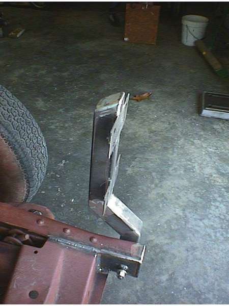
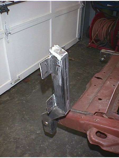
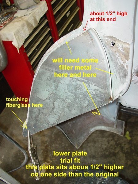
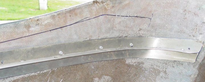
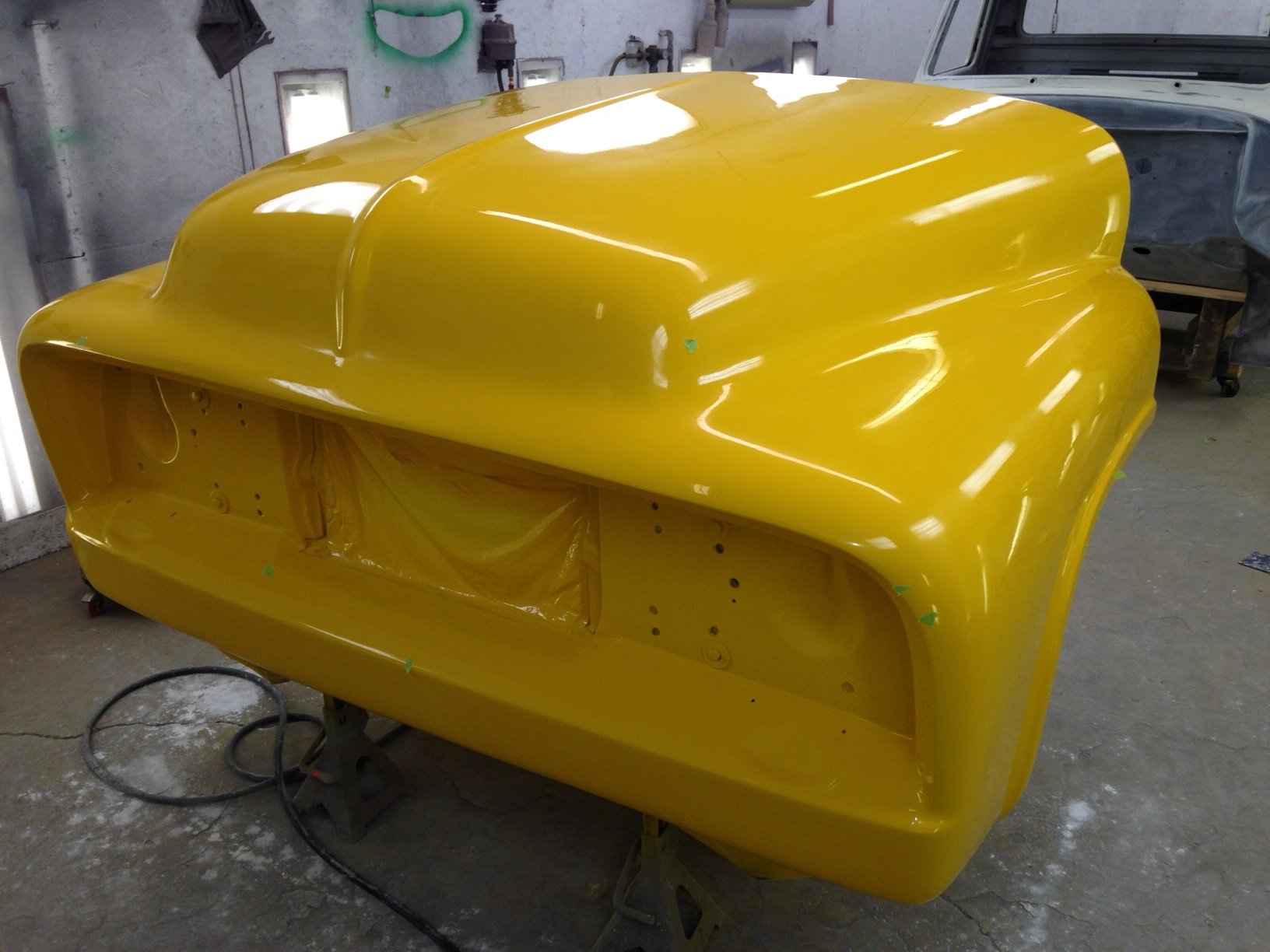
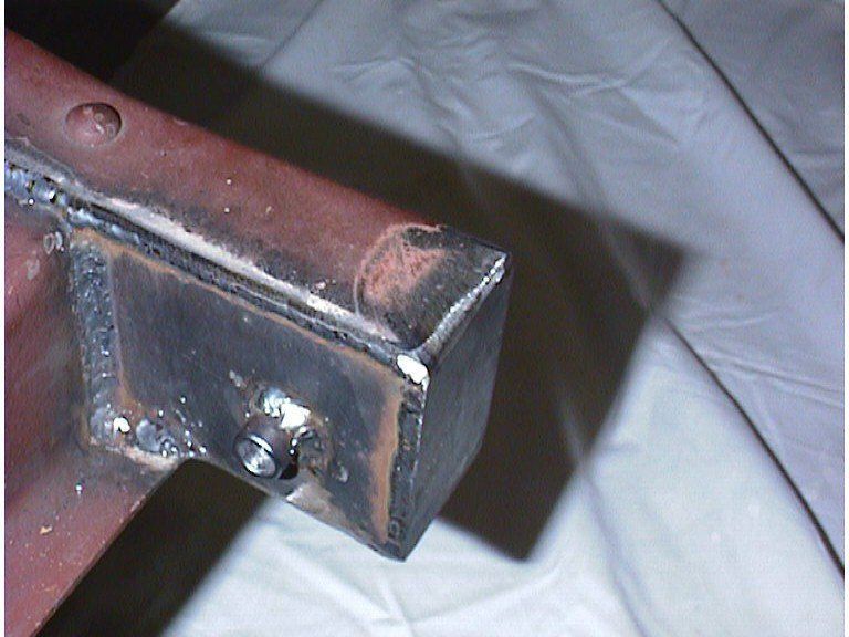
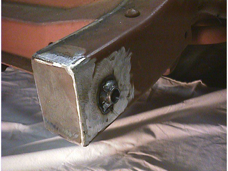
Tilt arms after adding mounting tabs and grinding the welds. Tubing was cut as shown at left. Bent to shape and welded. Mounting tabs were cut from 11 ga. (1/8") material and welded to the edge of the tubing

           tiltbrackettable1.JPG (19780 bytes)
           tiltbrackettableback1.JPG (18971 bytes)


After all the welds were made and ground smooth, the arms were cross drilled for the pivot bolts. I used ½" grade 8 hardware (bolts and locknuts). The holes were drilled so we cound insert a pipe insert with a 1/2" i.d..(5/8" o.d.) I reamed out the pipe for a tight fit with no slack or wobble on the bolt. The pictures below show a test fit on the left side

tiltbracket.JPG (59451 bytes)               tiltbracketfront.JPG (55770 bytes)             tiltbracketside.JPG (52832 bytes)             tiltbracketback.JPG (46166 bytes)

When both arms are installed onto the frame rails and the front flip kit is put in place for a test fit, adjustments will be made and cross arms could be added to tie the two arms together and add rigidity to the tilt unit.

The two tilt arms were drilled with two holes in each mounting tab for 7/16" bolts (a total of 16 bolts) and a backing plate was cut from 3/16 plate (7" x 10") with holes drilled to match. When all of this is assembled and bolted together it gives a very secure mount and spreads the load over a total of 140 square inches… instead of a few square inches that bolts with fender washers would provide. Fairlane cautions its customers about applying too much torque to the mounting bolts and crushing the fiberglass… this will lead to failure at the mount point. Pull them down tightly but don't test the limits of your torque wrench.

The air deflector of the Fairlane unit is extremely rigid and after mounting the plates to the hood and tilt arms, we were very satisfied that no other reinforcement or even cross arms would be necessary. The unit lifted easily from one side with one hand and showed very little flexing or bending.

                 leftinside1.JPG (123447 bytes)                                                           frontplate1.jpg (85511 bytes)

So… now we have the hood mounted to the tilt arms and it's working quite smoothly in the 'manual' mode.. but remember the 'cool' part….it's got to do it in the 'automatic' mode to be cool…


To make the 'cool' part we're using a electric screw actuator. The unit was originally used to raise the cover on a computer plotter and operated at 24 volts dc. Running it at 12 volts dc gives a perfect raise speed and I would imagine the motor would last longer ??? Either way it works well for my purpose… has plenty of torque… and is very quiet. An added bonus to electric over hydraulic is the absence of pumps, hoses, reservoirs and leaks.. just two little #12 wires that will tuck nicely inside the frame rail. The original plan was to use two motors, but after we saw that one handled it easily.. we decided to KISS it. (keep it simple, stupid).

actuator.JPG (16819 bytes)


I'd like to say that it took complicated calculations with torque figures and curve radii and geometry and protractors and such to make the tilt unit work properly. But, it wasn't nearly so complex. We had two actuators. We ran one all the way out and one all the way in and by raising and lowering the hood a few times and making some measurements we came up with about where we wanted to put it. The actuator has 4" of travel, which doesn't seem like enough to raise this unit. And, to admit it… I was concerned. We had already been discussing bellcranks and such during 'planning' sessions.

We welded a bolt temporarily to the frame and slid the actuator on the bolt. The pivot bracket was fabbed from a piece of 2" square tubing. I drilled the hole first then cut off the top side…rounded the sides to make it pretty. It was too wide so I cut 3/8" out of the middle and welded it back together. Ground the welds down and I had a neat little pivot bracket. We attached it to the tilt arm where we thought it should go, tack welded it and ran a bolt thru the actuator push rod and the bracket. For the test we hooked up a 12 volt battery, tensed up, closed one eye and applied the power, poised to snatch the cables loose at the first sign or sound of trouble. It was totally uneventful. The hood rose slowly and smoothly and reached its forward travel just about 1/2" before the underside of the hood roll pan touched the frame rails. It was perfect !! and on the first try !!! Dave turned to me and said "Ain't we somethin ?" What we were was lucky !!!

We played with it for a few minutes checking for binding and fit. We didn't change a thing. Welded everything in solid and stopped for the day…If you look at the pictures closely you'll see that I still need to weld in a cover/fill plate for the frame rail. We had to torch off the corner of the Volare sub frame to have a flat place to mount the cylinder. We'll fill in that hole with 3/16" plate and dress it accordingly.


                                       leftbracketcloser.JPG (40386 bytes)                               motormounted.JPG (37236 bytes)
 

This was a good stopping point… it was late in the day and we both had other chores to complete.All that is left is mounting the bottom portion of the fenders to the body and doing the glass work to dress them out.

A latching mechanism is planned for the center of the firewall. Something similar to a Caddy trunk latch or a Camaro rear deck latch that will gently pull down the hood when the latch hook contacts the latch. Limit switches will have to be added to cut the power to the actuator at full up and down limit, but that is electrical and not really a detail of 'mounting' the hood.

The remaining work includes mounting a latch mechanism to the firewall and some type of hook on the hood that will contact the latch.. mounting the lower portions of the fenders to the cab and glassing in the top openings.

As I have mentioned early in the article, the hood was a quality product but the fit at the cowl left something to be desired. I never determined that it was a problem with the hood or with the cowl itself because I don't know who's molds are more accurate, Ford's or Fairlane's. I suspect that Ford's molds in the '50's were less that perfect and there were inconsistancies in cab shape from one stamping to another... either way the fit was poor.

The Fairlane unit sat too high when the hood was closed. I talked to the Fairlane rep at the Supernationals last year and he suggested grinding the inner side of the hood down to fit... but no less than 3/16". I took a roll grinder on my electric drill and worked the inner lip across the width of the hood down to 3/16". That helped, but we still had a bad mismatch and there was no padding installed yet. There was also a problem with the fit on each side of the hood to the cab, the hood flaring out wider than the cab sides. So, we had three areas that needed work. The Fairlane rep suggested that the moldman might not have been as careful as he should have when he glued in the internal bracing. He told me I might try cutting the bracing loose, pulling the hood sides in more and regluing the brace... sounds easy enough... until you fit the hood to the cab, construct the hinges... and close it up over a 460 block !! There ain't a lot of room to work in there. We had to devise a different approach.

The main problem with the fit on the horizontal portion of the hood was on each side... the center of the hood fit well, but the two sides were definately too high.

 frontfit.jpg (57522 bytes)

Originally we thought we would cut the entire cowl area down about 1/2"... but after closer inspection we decided that we'd leave the middle alone and work on the two sides of the horizontal area from the corners in about 18".

Across the cowl there is a "rain gutter" for lack of a better term. It's a valley that runs across the cowl just in front of the air vent. In front of that is the raised ridge that the hood rests on. On the original hoods there was a piece of welting nailed (seriously, it's nailed) on here to prevent the hood from rubbing and sqeaking. With a plasma cutter we sliced thru the ridge of the cowl...around the front edge and in the wall of the valley. We left it attached at the center of the cowl and cut it across the edge. Then with a grinder we tapered the front edge down about 3/8". With a body hammer we brought the rear side of the cut (the front wall of the valley) down to match the height of the front edge. The only thing that remained was pulling the "cap" down and tack welding it in place. When we were happy with the fit.. we did the finish welding and it will be dressed with body filler later.

Below are the pics of what we did... they should replace a lot of these words...


                                                  rightcowl.JPG (85025 bytes)             leftcowl3.JPG (101032 bytes)
When we lowered the hood after this work it fit much better... the hood was lower then the cowl as we hoped, by about 1/4".. which will leave room for adequate padding. Now we had to work on the spread the hood had taken.

The internal bracing makes the hood extremely stiff and it had to be releaved before we could do anything else. We tried the Fairlane reps suggestion and using a hacksaw blade sawed through the glue holding the bracing to the hood. It was aggrevating because the blade kept bending, but wasn't that difficult as the glue wasn't uniformly distributed and gave up pretty easily. Once the brace was loose the hood was much more flexible. We cut the center section out of the bracing and it will be glued back in when we get the hood in it's final shape. The hood was easier to bend then, but still wouldn't take the shape of the cowl on the left side. We sawed a few kerfs in the hood at the curve which releaved it even more and it layed down next to the cowl perfectly.


insidehood3.JPG (122311 bytes)
The hood will be lowered and pulled in to match the shape of the cowl...when we get the fit just right we'll glass in the kerfs. After that has set we'll replace the center part of the brace and using a fast set urethane glue, we'll reattach the internal bracing to the hood to hold its shape.  The next step will be attaching and finishing the side pieces of the fenders. More to come.......


Ok, fast forward several years... lots of things got in the way of completeing this project but it's back on the table again.  As I mentioned before there were serious problems with the fit of this fiberglass hood.  I had several conversations with the original owners of Fairlane and a couple with the  last owner and nothing was offered as a solution.  Sadly Fairlane is out of business now.


I've inlisted the help of a fiberglass expert and an excellent body man who's helping get this thing finished.  The rest of the truck for all purposes is ready for final blocking, primer and paint... if (no, when) we get this hood perfect we'll be all set.  As mentioned above we removed all the bracing from the hood and we've got the gap at the hood edge/cowl acceptable.  The next step was to add the lower fenders to the cab.  But, to do this it was necessary to mount the bed, the rear fenders, the running boards and get all this in alignment so the front lower fenders cound be set in the proper place.

bed71.jpg (1817977 bytes)

With  these pieces in the proper place we could attach the lower fenders to the cab to line up with the hood and still maintain the proper relationship to the running boards.  We held them up in position  and found a few more flaws in the fit.  The edge of the fender (flange side) didn't match up with the cowl when it lined up with the hood... there was a gap between the fender and the cowl.  We had to add filler to build up the edge of the lower fender to make it line up as it should.  We made it fat and sanded it down utill we were happy with the fit, and then  scribed a line on the cowl to mark their position.  Then we drilled the fender flanges and marked the holes on the cab.  In a couple of places the original fender mount holes were used, but in a couple we had to drill new holes.  We added bolts, fender washers and nylock nuts and they were attached.  This, like every other step in this process was time consuming, but we wanted a good fit and it was necessary. 

fenders005a.jpg (434702 bytes)

After the fit up was acceptable we discussed  the final look some more and it was decided that the fender would look much better molded into the cab instead of the customary line that usually contained welting.  Kitty hair was used as a base layer followed by regular fiberglass filler for the final coat... even under the fender where the seam was was smoothed some for a better appearance.

fenders002.jpg (389174 bytes) fenders004.jpg (499947 bytes)


After both of the fenders were attached the next step was to fab/mount the cover plates for the top of the fenders... this isn't absolutely necessary but it does dress it up a little more instead of having the hole just hanging out there.

Our first plan was to make the covers from fiberglass covered base board (cardboard) and glass them in and they looked fine...  but when we were working on the matching plates for the hood we ran into some problems and scrapped that idea.  Plan "B" was to fabricate them from metal.  Quicker and easier... here's a shot of the fiberglass top plates in the fender holes

restart1.jpg (440066 bytes)

We decided to leave the fiberglass plates in place and just install the metal plates over them.  They will be dressed up pretty and you'll never know the difference, plus it was easier to do that than rip all the old stuff out and start from scratch. 

Our problem with the hood plates was that we didn't pay enough attention to the alignment of the plates in relationship to the hood itself.   Originally we just made the lower fender plates and didn't give any thought to how they would line up with the hood plate... and where we had them is what kicked the hood plates out of alignment... we matched them to the fender plates.  (hey, don't laugh, this the first attempt at this for both of us !)

We were so concentrated on the fit up close that we never stepped back to see the overall...  I walked up to the truck one day while we were working and noticed that the hood plates were sticking back toward the cab (badly ) when they should have been perpendicular to the hood side...  The bad part is I didn't notice it until one side was completely finished.  That's what made us decide to rip it out and use metal...   one step forward..two back.  To keep from making the same mistake twice we pulled alignment strings from one side of the hood to the other to maintain the correct angle and keep the two plates parallel.


restart2.jpg (566582 bytes)

restart3..jpg (547903 bytes)

Once we fabricated the plates to fit and curve of the hood we welded 90 degree tabs onto the back side in three places then screwed them onto the hood and bent them to align with the strings.  The screws will be removed after the plates are glassed into the underside of the hood. 

Now that the hood plates were installed and aligned properly it was time to 'adjust' the fender plates to match them. (what we should have done in the first place.  As I said we decided to leave the fiberglass plates and just put metal plates over them.. The fiberglass will only serve as a strengthening brace for the lower fender. 

Here's a pic of one of the lower plates being trial fit.  

restart4.jpg (695451 bytes)


The next step was to add in filler metal around the metal plate to blend it into the fender and then glass it all to make it pretty.

hood 005.jpg (544916 bytes)


This is about where we are now... the passenger side lower fender is ready and the first wipe of kitty hair is on the drivers side.  We still have to work the hood plates. 


We can't do much with the final alignment of the hood to the fenders and the cowl until we address the shape of the hood... or the profile matching the cowl and then the structure needed to keep it in that shape.  In the first of the article you saw that we removed all the bracing because it was holding the hood in the wrong shape relative to the cowl.  We've found a solution and pictures and words will come soon.  And it's all thanks to another truck owner who has traveled this road and found the path for us to take...  thanks, Terry !!


more to come...


and here it comes....   we had cussed and discussed the fit of the cowl until we were both frustrated and quit.  We had to have something that absolutely held the shape of the hood  so it matched the cowl shape and nothing we had tried worked.  I was walking around the Supernationals in Pigeon Forge in 2012 and found a beautiful truck with a tilt hood (and bed) and of course looked at the hood first... He had installed a louvered Stainless Steel inner hood cover that really dressed it up but what I saw that really interested was a stiffener he added to the inside of the hood.. We discussed it at length and he had the same cowl fit problem and after a couple of attempts he came up with this...  he determined the shape he needed from the cowl profile and cad designed  and cut the shape into the stiffener metal... then added a top cap to mount it to the hood. 

hood01.jpg (1710455 bytes)
stiffenershape.jpg (72805 bytes)


So, after discussing his design I asked if I could pay him to build one for me since he was set up to do it...He laughed and told me I couldn't afford him.  It was a trial and error project.  But he said he had another prototype he would give me and I could try it !!!!!   Addresses swapped and a week later I'm screwing it inside my hood.


stiffenerin.jpg (29993 bytes)


stiffenerin2.jpg (48683 bytes)

When we lowered the hood down to the cowl... it was a perfect fit !!!!!  and the fender/hood edges lined up perfectly also...   our problem was solved.  There will be some dress up filler work to make it complete but the major hurdle was overcome...  again THANK YOU, TERRY !!!  That's what I love about this hobby... good folks that will help a guy out.... even a stranger.

So, our hood is FINALLY matching up with the cowl, the filler pieces for the hood and lower fender are complete... other than sanding and final filler/blocking...  there is still some filler work needed on the inside of the lower fenders... and the whole inside of the hood will be ground down, filled and made to be slick and pretty...  (that's gonna be a chore). 

We blew the whole truck apart again and started working on the firewall, kick panel and cab bottom... all the misc holes will be filled and a smooth firewall will look fine. 

IMG_0376 (2).JPG (96050 bytes)

The kickpanel and cab bottom were coated with "Monsterliner" undercoating in the appropriate color... yellow


Img_0389.jpg (36432 bytes)


and the cab/hood will be ready for blocking and prime followed by more blocking and paint.   Pictures below show my bodyman working away and the inside of the hood ready for hi-build primer


IMG_0854.JPG (511772 bytes) IMG_0980.JPG (108608 bytes)


This shows the inner side after the first coat of Slick Sand Primer. Still have the air dam and all those little skinny places that need hand sanding, but it's getting there... I will not admit to how many gallons of filler were applied and removed... I swept up a lot


Img_0961.jpg (163771 bytes)


Img_1129.jpg (186846 bytes)

at this point it was off to the painters with the rest of the truck...


and here it is

Img_1963.jpg (217527 bytes)


Img_2058.jpg (400299 bytes)


Img_1950 - Copy.jpg (162501 bytes)


Img_1987.jpg (259596 bytes)


Img_2060.jpg (259596 bytes)


kinda hard to see the pretty ghost flames but they are there


here's a little video of the hood comin down

https://www.youtube.com/watch?v=El0e6HfCS7c


THIS HAS BEEN A LOOOOOONG HARD ROAD.  Tilt hood owner wannabe's...beware.   and you might notice the copyright date below... that's when this project began.


Copyright © 2001 John Niolon

All International Rights Reserved. This document may not be copied or published without prior written consent of the author.

This work was done by me and for me. I only ask that if you reproduce it give me credit for it and if you make money from it… give me my percentage.

Since I have no way of knowing your level of competence, welding or cutting skills or mechanical ability….there are no guaranties or warranties either verbal, written or implied with this article. Pictures were made at different stages of construction and all parts in pictures may not be complete in each shot, but I’ve tried to make the plans or drawings complete to the best of my ability. If you have questions or see mistakes or problems, let me know by e-mail and I’ll make the corrections if possible..

Use these ideas at your own risk. Modify them at your discretion and to suit your purpose. Your mileage may vary…. batteries not included…. much assembly required…. wait one hour after building to enter the water….additional charges may apply…. not all applicants will qualify for advertised A.P.R.….for ages 10 to adult…. side effects are comparable to placebos…. Do not take drugs when building or operating this machinery...just say no !

John Niolon

3700 Virginia Drive

Hueytown, Ala 35023

jniolon@att.net