After purchasing
a new trailer to replace my favorite that was stolen I realized something quickly…
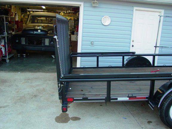
this new one had a drop tail gate/ramp that my old trailer didn’t have. Now, I’m no sissy… but this gate was
rather heavy and my back has seen enough abuse over the years that I saw the need for some
assistance lifting the gate. Since someone
isn’t always around to help me lift it, I looked for a mechanical solution.
Searched the net
and found several different solutions available. From
leaf springs to coil springs to hydraulics. Some
were simple, some rather complicated, some even scary.
But one thing they all had in common… they were all expensive. After looking at several different models I decided
on fabbing up one using garage door springs and some 2” x 2” square tubing I had
on hand. Here’s what I’ve come up
with. It easily resembles the outward
appearance of a readily available patented commercial unit… I don’t know what
their insides look like…but I built mine for about 1/2 the cost.
Introducing… pretend you hear a drumroll here
THE
GIRLY GATE.
A friend with a
lawn maintenance business uses the commercial model, his hired help dubbed it the
‘girlie gate’ since he added it after his wife came to work for him and the
assist was a nice addition for her. So
I’m stealing his name for my tailgate lift assist contraption.
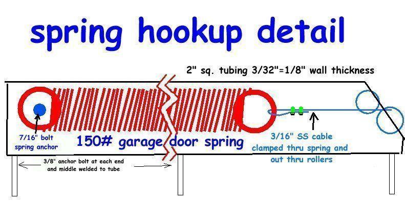
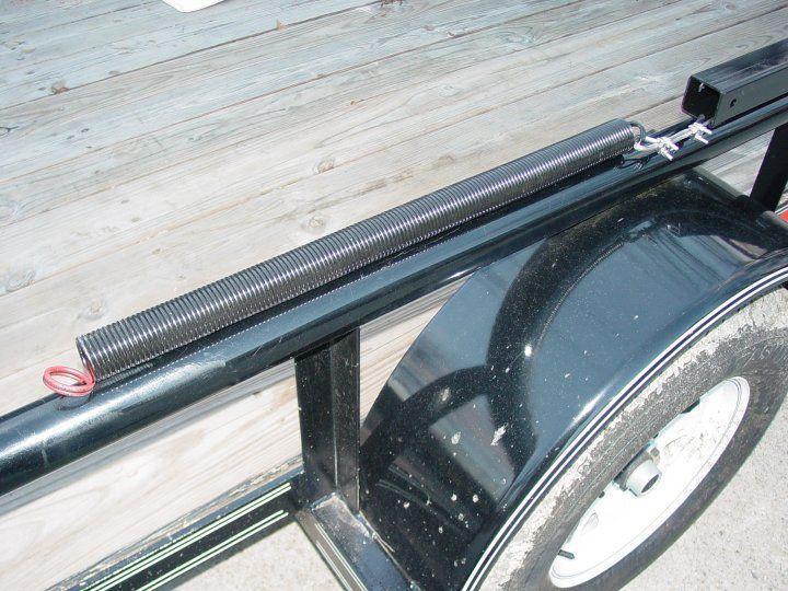
The basic unit
is a length of 2x2 tubing on each top rail of the trailer, which encloses a set of garage
door springs, some cable and some rollers to guide it evenly. A list of material follows, so you can start
gathering, scrounging, borrowing, appropriating or buying the stuff you need.
2 pcs |
2” x
2” Square Steel Tubing – 72” (or so) long |
wall thickness
can be anything from 14 ga up to 1/8” or so …the only critical part is that the
spring will slide inside the tubing without binding |
2 ea |
150# Garage
Door Springs |
These have a
“RED” color code on each spring end loop. You
can find these at any big box home improvement store… Home Depot, Lowes, etc. |
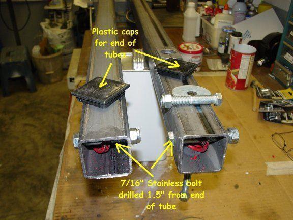
2 ea |
7/16”
2.5” Stainless Steel bolts with nyloc nuts |
Stainless will
last longer and not rust. I like the nyloc nuts better than lock washers and standard
nuts... |
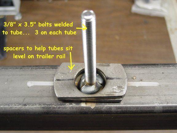
6 ea |
3/8” hex bolts and nyloc nuts |
Anchor Bolts
for tube to trailer. Length depends on the
thickness of your top rail. I have a 2.25” round top rail so I used 3.5” bolts. |
2 ea |
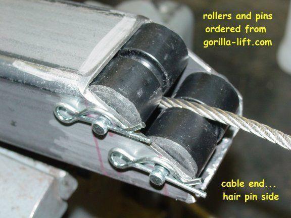
Roller kit |
I used the
roller kits available from Gorilla-lift; it contains two rollers, pins, washers and
hairpins. They are already slotted for the cable. |
15 ft. |
3/16”
diameter Stainless steel cable |
Your length
might vary. I just bought enough so I wouldn’t have to make another trip to the box
store. |
8 ea |
3/16”
cable clamps and (4)thimbles (also called eyelets) |
Again
Stainless is better. |
2 ea |
Plastic caps
for tubing |
This is
optional… but I had the caps to fit into the anchor end of the tube… keeps out
the weather and looks neater. |
2 -4 cans |
Paint/Primer |
Use a good
quality enamel primer and paint on your tubes… your choice on color. I painted mine to match the trailer… gloss
black |
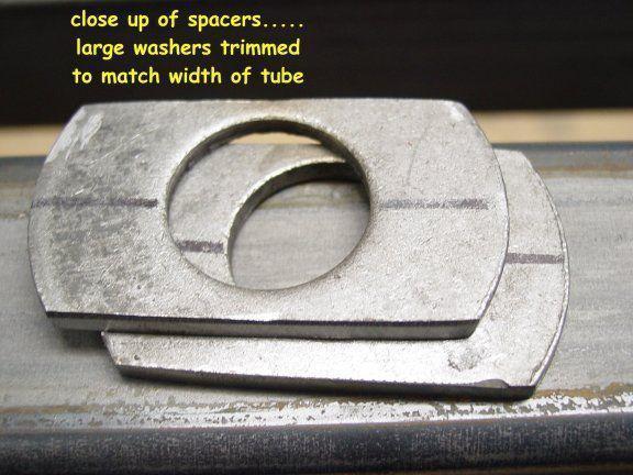
12 ea |
Large washers |
See article
for use in mounting tube to trailer |
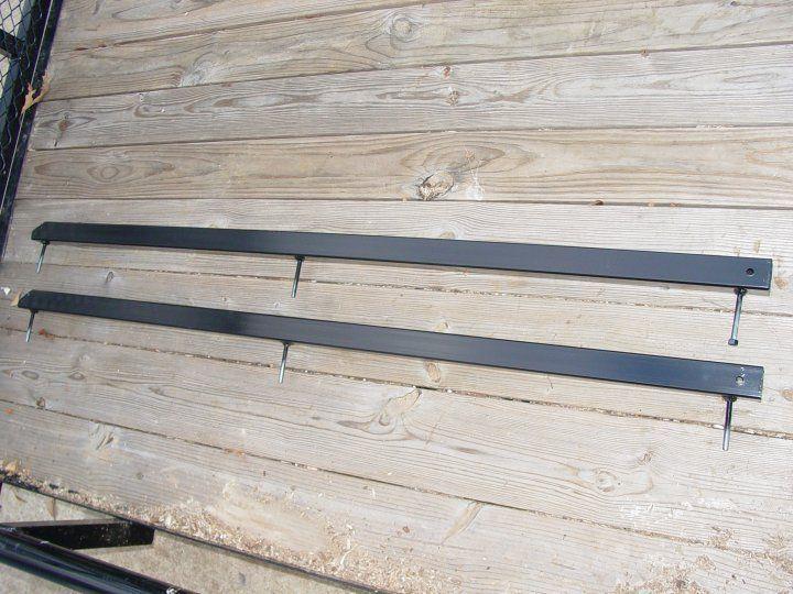
I started with
two identical tubes 72” long, but after some trial and error blunders; it ended up
being 70 inches long. I measured incorrectly
for my roller mounts; and had things too tight in the tube; the rollers would not turn. The length isn’t that critical as the spring
will never extend to the end of the tube anyway.
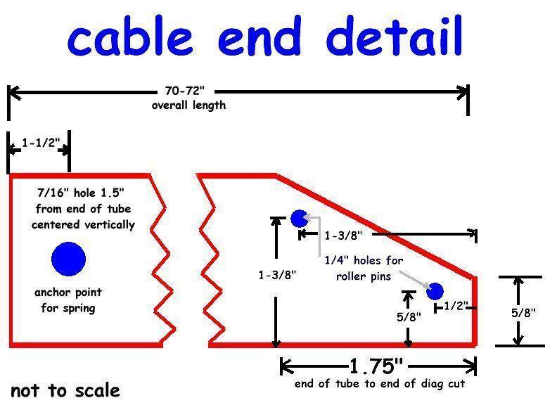
The measurements on other end need to be a little more precise to assure that the rollers will in fact turn and will not bind up in use. The original rollers were just a bit too long to fit inside the tube. (Gorilla-lift uses thinner wall tubing) I held the ends of the rollers against a belt sander and shortened them about 1/8” (a 1/16 or so on each end to keep the slot in the middle). Then I opened up the hole (thru the roller) for the pin slightly to allow a little easier rolling on the pin. Look at the drawings below (SPRING HOOKUP DETAIL) to see the overall assembly of the assist and then the (CABLE END DETAIL) to see the cut dimensions for the roller end of the tube… NOTE…the measurements in the “CABLE END DETAIL” work with 2” square tubing with a 1/6” or so….The tubing doesn’t HAVE to be 2x2… that’s what I had and it looked decent on top of my top rail. If you use tubing with different dimensions or with a thicker or thinner wall… the dimensions in the drawing probably won’t work… your tube size and roller dimensions will determine the proper placement of the roller holes.
After the cuts
are made, layout your holes for drilling and drill them using a drill bit one size larger
than the pin size (i.e. 9/32” for a �” hole).
A drill press will do a nicer job of keeping the holes aligned thru the
tube. You can drill right through the second side easily while keeping holes straight. It’s easy to get out of plumb with a hand
drill when starting through the second side. Take
care with these holes, the rollers need to be parallel and the correct distance apart or
they will bind.
Once you have
the holes drilled and have tested the rollers for free movement it’s time for
assembly… (see??..it’s not rocket science)
We need to
assemble the spring/cable assembly before putting the spring inside the tube
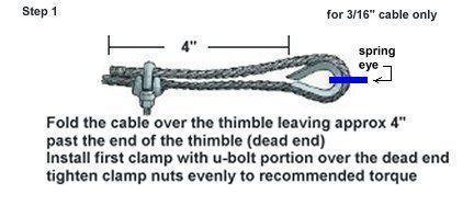
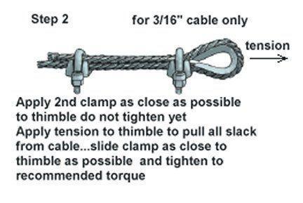
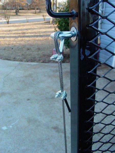
First we need to
attach the cable to the spring. Slide the
thimble thru the spring eye, and then clamp the cable around the thimble as follows
The easiest way
to put the spring/cable assembly in the tube is to remove the rollers and thread the cable
from the anchor end thru the tube until the anchor end of the spring lines up with the
anchor bolt hole. Then you can install the
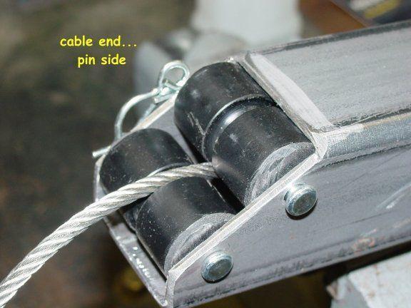
rollers threading the cable thru the slot in the rollers.
Install the anchor bolt at the tail end… put the hair pins in the
roller shafts… and bada-bing… it’s done.
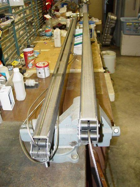
I put on a pair
of gloves, tightened my tube down in the vice and gave a test pull or two… nice
smooth action and the springs ‘feel’ plenty strong to lift the gate… that part comes next.
Mounting and
adjusting.
You can assemble
the thing on the bench and install it that way… since mine was apart for paint I
installed the tube then put all the pieces inside it..
your choice there…
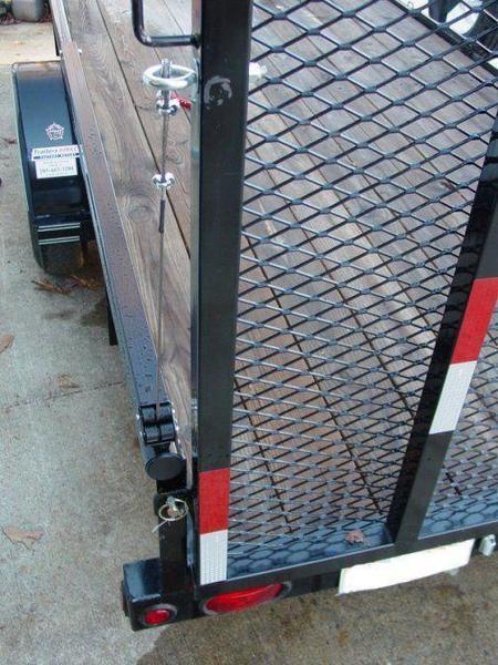
Tighten the
tubes down securely to the rail using nyloc nuts..
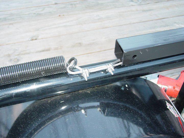
If you’re doing it in pieces the next step is to insert
the spring/cable assembly into the square end of the tube and secure the spring with the
cross bolt. The cable should be dangling out
the roller end of the tube.. Put the plastic end cap on the square end if you have one
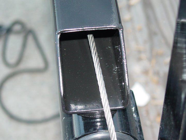
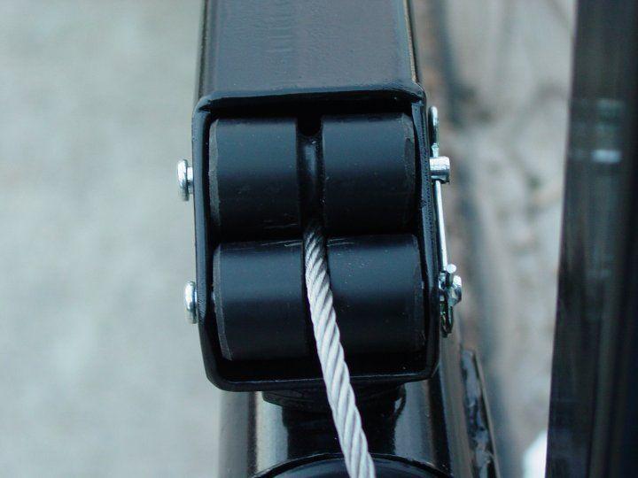
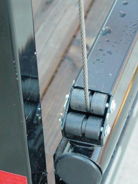
Go to the other
end of the tube and install the rollers with the cable sticking out between them… put
the hairpins or locking pins thru the ends of the roller shafts… make sure the
rollers turn easily. A little light oil or
grease on the innerds of the rollers/pins wouldn’t hurt, but I wouldn’t get
carried away and make a mess that will get all over the cable and you… optimum word
here is ‘light’
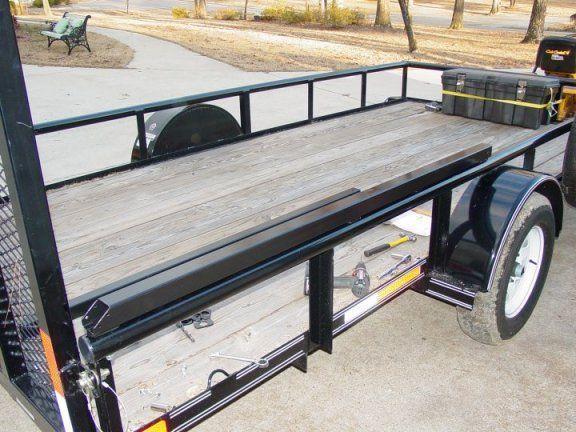
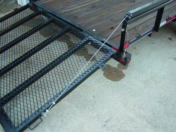
The GIRLIE GATE is now officially installed… now to connect it
to the tailgate/ramp.
Tailgates/Ramps
made from Angle Iron |
Attachment point
** |
4 feet high |
17-18 inches |
5 feet high |
26-27 inches |
6 feet high |
29-30 inches |
Tailgates/Ramps
made from square tubing |
Attachment point
** |
4 feet high |
22-23 inches |
5 feet high |
27-28 inches |
6 feet high |
29-30 inches |
** this
measurement is made from the top of your side rail
(where the tube is
mounted) to the attachment point
That pretty much
does it… Some cautions and advise… NEVER travel with only the Girley gate
holding the gate closed… ALWAYS use the
appropriate pins/bolts/latches etc to secure the gate in the upright and locked position. This device is intended to be used solely to raise
and lower the gate when the trailer is stationary… not going down the freeway at 70+
mph.
Boilerplate
denial of liability statement…
This device is
something I came up with to prevent me from spending too many dollars on a commercial
patented device, it is not patented,
engineered or even perfect… it is what it is, a home made contraption. I’m sure there are alternatives to this design
some even better/cheaper/easier, I just didn’t think of them or warrant them
necessary... there are several similar units on the internet waiting behind Google for you
to see/copy/build…(just like I did) This work was done by
me and for me. I only ask that if you reproduce it give me credit for it and if you make
money from it… give me my percentage.
Use these ideas at your own
risk. Modify them at your discretion and to suit your purpose. Your mileage may vary,
batteries not included, much assembly required... wait one hour after building to enter
the water, additional charges may apply. not all applicants will qualify for advertised
A.P.R., for ages 10 to adult…side effects are comparable to placebos. Do not take
drugs when building or operating machinery. JUST
SAY NO.
Copyright . 2011 John Niolon,
All International Rights Reserved. This document may not be copied or published without
prior written consent of the author- jniolon@bham.rr.com