First, when I say Volare clip It referring to any Chrysler product front clip, Grand Fury, Diplomat, Fifth Avenue, etc., with bent torsion bar suspension that is bolted to the frame of the car. Secondly, let me begin by saying this is by no means a how to article. I'm not smart enough to write that on this subject. It's only a collection of thoughts and comments on what we did and how we did what we did when installing a Chrysler Clip in a '53 F-100. My original pictures weren't complete I didn't take enough in the beginning stages...we were busy cutting and grinding and stuff. But, through the generosity of Sam Detweiler, we have new pictures that show the placement of templates and the initial cuts in the frame from the templates. Sam recently did this install and was smart enough (more so than me) to do a good job of documenting it. Sam also used the video that No-Limit Engineering offers and got quite a few tips from it about measurements and fit-up. I think this would be a good investment for anyone considering this installation Sam's pictures should add quite a bit of detail to this article and make it much more useful So, take it for what it is and I hope it is useful to some of you. Second, there are several excellent articles in Classic Truck and Custom and Classic Truck Magazines over the past few years on this subject with very good pictures. I used one of these articles to guide me in doing mine. I attached a list of the magazine name and month of article on the tail end of this. I've copied these articles for some people and sent pictures to some...so I thought I'd finally write down everything I could remember and stop doing this over and over. So it begins... I chose the Chrysler Clip for a number of reasons. I wanted IFS and good braking.. I've driven enough old stuff with straight axles and Armstrong Power Steering to know that's not how I wanted to go. Wandering between the stripes and hoping it would stop tends to cut down on my driving enjoyment. There are several very nice after market kits out there that offer IFS and disc brakes. My number one criteria was cost. You can purchase a complete clip including steering box, power steering pump, hoses and in some cases rims and tires for under $200.00 at most salvage yards. Depending on your bargaining skills, and your relationship with "the man", maybe less. Compared to the trick IFS kits the after market offers at 5-10 times that price, it's a no brainer for low dollar builders like me. It serves the same function and unless you're jacking up the truck and laying down mirrors under it at a show. Who's gonna see very much of it anyway ?? Number two was convenience. The clip is complete. No searching for components from Chevys and Mustang II. It all comes with the package. Number three is ease of installation. With a set of templates and good welding skills, even a rookie like me can do this. Ok, I didn't do the welding. I have a friend who is an EXPERT welder and he was also interested in a Chrysler install on his truck. Mine was the guinea pig ..err Learning tool. Choosing the donor Chrysler has used torsion bar units for decades...the earlier units used straight torsion bars that mounted to the frame rails. The later units (80's and up) used a bent torsion bar that is totally contained in the front clip assembly. This is the one you want to use. Especially if there will be a big block anything riding over it. I was told by a Chrysler front end "expert" that any rear wheel drive Chrysler, Dodge, Plymouth product from 1984 and up was a V-8 and is a suitable donor. The bottom line is ...if it was a slant 6, V-6, transverse don't use it ! BUT, I was told by another knowledgeable Chrysler person that the slant-6 engines weighed more than some of the Chrysler V-8s ( the 318 ) !!! The V-8 units are probably stiffer and for sure the police units were the strongest of all. As far as I can determine, and I've called at least 20 Chrysler sourcesŊ there is no table or listing of torsion bar sizes that specifically says that Ŵhis size bar fit a slant-6 and that size bar fit a V-8. The consensus is, the only way to tell is looking at the engine mounts. Chrysler used a funky tower type engine mount that was welded to the front clip (Chrysler calls it a K-member, go figure). The slant-6 mounts were of unequal height, the passenger side being higher than the drivers side. The V-8 units were of nearly equal height. I guess the best way is to scrounge the yards...find a car with the engine still in it, with no front end damage, and point to the man and say "This one". Getting Ready. The first step is to take some measurements and make some marks. Find the axle centerline. Using a plumb bob and line or a square, transfer the axle center line from the axle body to the frame. Punch this center line on the frame and scribe it on the side of the frame rail. It wouldn't hurt to take some reference measurements to the rivet heads right under the firewall and write them down somewhere, just in case you get rowdy with the grinder or something and remove your marks from the frame. Sam mentioned that NLE used the snubber hole as the axle centerline. Ŵhat's easy enough ! Stripping the frame Next is to strip away all the straight axle stuff. Springs, shocks, axle, spring mounts, snubbers, and the drip pan behind the front cross member (and under the radiator) Everything till you have a clean set of frame rails to work from. I'd even go as far as pressure wash, steam clean or sand blast if it's convenient. I steam cleaned my whole frame before we started, but waited till the clip was in before the sandblast and prime stage. From the pictures you can see I had an empty frame and it makes it so much easier. My buddy Doug (the welder) did his under the fenders...didn't remove any of the front sheet metal. You can do it that way.. but measuring, sliding, clamping and grunting are much easier without the sheet metal in the way.. |
|||||||||||||||||||||
 |
|||||||||||||||||||||
 |
 |
 |
|||||||||||||||||||
Marking your territory. Before you make your first cut, you should level the frame. Front to back and side to side. Set it up on jack stands and shim between the stands and the frame until it perfectly level on both planes. If the frame is cleared of cab and bed, now's a good time to do some diagonal measurements and see that it's square and not twisted out of shape. If it is far out of spec, I don't think I'd attempt to weld in the sub frame until the frame is square. I don't know what the actual tolerance is...mine was within 1/4" of square and best we could tell with minimum equipment, it wasn't twisted at all. (We set up a level and took readings on each corner of the leveled frame.. everything seemed to be flat with no twist..(poor mans frame machine ???)Templates for the cut are available from some of the custom truck shops. Bobco or Bobҳ F-100ҳ has them as well as some others. There are some videos available also. I would strongly recommend investing in templates. They are worth the cost as they give you specific measurements and reference distances to rivets and frame holes. They make the job much less daunting when you light the torch. Some will include boxing plate templates and some don't. Mine didn't, but they are easy to do after the sub frame welding is complete. The templates also have the proper rake and setback for the axle line built in. Makes the placement a breeze. |
|||||||||||||||||||||
 |
 |
 |
|||||||||||||||||||
 |
|
 |
|||||||||||||||||||
| Transfer
the template outlines to the frame rails... scribed or soap stone. Check your measurements
to the reference points again. Walk around it and look at it, does it "look"
right ?? Go get a cup of coffee or a beer and think about it. Check your measurements to
the reference points again. Look at the templates one more time and lay them on the frame
to check your marks. Do the frame holes and rivets line up correctly ??? Check your
measurements to the reference points again. I know this sounds like I'm saying you'ee a
dummy, but once you cut it wrong. It's extremely hard to fix. Is it right ??? Apply
striker to torch tip !!! Doing the deed Don't fret the torch... if you aren't comfortable with a torch you could use a saw !!! But remember, the straighter and cleaner your cuts, the less grinding and filling you have to do. The cuts are simple... looking at the side of the frame, a notch is cut out approx 1-1/2" high (from the bottom) at the front of the notch( at the front cross member) and about 1/2" high at the rear... the cut is the length of the sub frame... approx 18"-20" or so. The difference in the depths is to give the sub frame a rake to the rear. Sam's pictures below show the frame after the cutting process. |
|||||||||||||||||||||
 |
 |
||||||||||||||||||||
 |
|||||||||||||||||||||
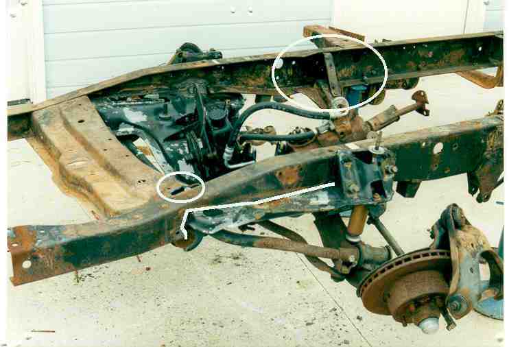
The picture above is of my frame after the clip was tacked in. It shows a line on the frame rail, this is the approximate cut line. Sam's previous pictures show it much better. The reason for this shot is to point out a couple of thingsŮThe circle on top of the rail shows how the front cross member must be notched for the torsion bar adjuster. The other circle on the other frame rail shows the rear cross member. This can be removed AFTER the sub frame is completely welded in. The sub frame will give the frame all the strength it needs in the front now. The templates will give you a very close fit (if you can follow the cut lines closely) but some grinding will be needed to get a perfect fit. The closer you can fit it , the less filling you have to do with welding rods. We tried two different ways to put the sub frame under the frame. First was a cherry picker (engine hoist). We slid the sub frame under the frame and lifted it into place with the cherry picker and chains. It worked fine and gives you movement in small increments and the load is balanced. You can also use a floor jack ...set the sub on the jack, roll it under and jack it into place.. It's a little more precarious on the small jack pad but it also works. One point I didn't mention... the templates we used set the new axle center line 1" forward from the original. This positions the tire more in the center of the wheel opening and gives the truck a little better appearance.. this is explained in one of the articles very well.O.K. so now you've clamped it in place and checked your measurements one last time. Right ??? Check your measurements to the reference points again. Walk around it and look at it, does it "look " right ?? At this point if you do it wrong it's even HARDER to correct. If you're happy with it, start your tack welds. Weld it at each corner, inside and outside the frame rails. Then ??? Check your measurements to the reference points again. If you're still happy, make it permanent. We used a Lincoln 225 amp AC./DC welder on DC settings. I'm sure you could use TIG of MIG although some of the areas, like between the control arm towers and the frame are less than 1/2" wide. That's a little narrow for a mig torch. We used a 6010 rod for the root pass (good fill characteristics and works with dirty or rusty metal well) and a 7018 (low hydrogen) for the fill passes. Don't start at one end and weld to the other.. move around and weld in different places. If you concentrate too much heat in one area things will start to move and twist around. Use 2-3" passes alternating on opposite sides and opposite ends. Until you have a complete weld. We welded inside and outside the frame rails. Note: If you don't feel confident doing this welding, by all means find someone who can do it properly. This is what keeps your truck in the road. At 70 mph (or more ), around curves,making hard stops and hard starts, you need to trust the welds. I was fortunate to have a good friend who is a master pipefitter and an expert certified welder and he has a '5ҵ5 also. He's responsible for the nice welding on my truck.After the sub frame is welded in, slag chipped away and welds prettied up, I'd shoot a coat of primer and paint on the welds (maybe Corroless or POR-50) before I installed the boxing plates. Holds down the rust and it looks better. Boxing plates If you have templates for the boxing plates.. good. If not, they are easy to do with cardboard and a pencil. Keep your grinder handy. We used 1/8" plate set just inside the frame rails. We boxed from as far forward as we could to about 12" behind the sub frame. You'll have to notch around the torsion bar adjusters a little and probably around the steering box if you're using the Chrysler box. Look at the pics to see ours. This adds a lot of strength to the front end and combined with the sub frame, the front end is very rigid. Fish plates Under the frame rails where the front of the sub frame contacts the frame is where the largest amount of metal is cut away. The magazine articles mention this and I agree that some gusset plates should be added here to reinforce the front of the frame horns. It's hard to explain how to do it but, cut and fit some 1/8" plate that will fill in the void areas between the frame rail and the sub frame. Both on the horizontal and vertical sides of the frame rail. It's not a very large area but it needs reinforcing. It holds up the front end of the fenders, hood, grill and bumper...so why not ??? |
|||||||||||||||||||||
 |
|||||||||||||||||||||
| Finishing up About all that's left is the cleaning of welds, primer and painting. Except for engine mounts. The Chrysler clip has some funky mounts down low on the sub frame that are just in the way.. Wash them off with a torch and you'll have plenty of room to fab up whatever you need for you engine.. these shown above and in the other pictures are for a 460 c.i. Lincoln engine |
|||||||||||||||||||||
 |
|||||||||||||||||||||
| Some folks opt to remove the Chrysler mounting ears and make
filler plates for the holes...their reason is that someone will invariably try to jack the
truck on these ears, bend them and they look bad. Personally, I'll be the only one jacking
my truck and I know better. The Chrysler bolt pattern is 5 x 4-1/2" which is
different from the Ford 5" or 5-1/2" I was having rear axles shortened and
resplined so I just had them redrilled at 4.5". That way I can carry one spare tire.
Your conditions may vary from this. ༯td> |
|||||||||||||||||||||
| Article
list ༯p>
|
|||||||||||||||||||||
| Below are some other shots of my job and Sam's maybe
they will give you some different angles to see what was done. This is my unit after tacking it in |
|||||||||||||||||||||
 |
|||||||||||||||||||||
| Outside drivers side of my clip after finish welds | |||||||||||||||||||||
 |
|||||||||||||||||||||
| Passenger side of my clip... finished welds and control arms installed. | |||||||||||||||||||||
 |
|||||||||||||||||||||
| Inside passenger side showing boxing plates and 460 ci.i motor mounts | |||||||||||||||||||||
 |
|||||||||||||||||||||
| Inside drivers side showing boxing plates and steering box installed...also motor mounts | |||||||||||||||||||||
 |
|||||||||||||||||||||
| This is Sam's clip tacked into the frame. | |||||||||||||||||||||
 |
|||||||||||||||||||||
| I've blanked out the background (as much as possible) to give you a view of what the subframe looks like when taken out of the Chrysler. The upper control arms are missing in this shot and the steering box but it gives you a general picture of how the unit looks and sits. The four round holes at the corners are where the unit mounted with rubber donuts and bolts to the chrysler frame. | |||||||||||||||||||||
 |
|||||||||||||||||||||
| This is Sam's unit after tacking in from left side ...you can see what a nice job he did on the frame cuts..not a lot of weld fill will be necessary. Notice the level across the frame rails this was mentioned in the article> | |||||||||||||||||||||
 |
|||||||||||||||||||||