| INSTALLING SPECIALTY POWER WINDSHIELD WIPER KIT IN A '53 F-100 |
| A.K.A. MID-50 POWER WINDSHIELD WIPER KIT Part #:93039-5355 |
| by John Niolon |
I bought this kit from Mid-50 (www.midfifty.com) several years ago at the Supernationals... just got to the point where I was ready to install it. That point being BEFORE I install the Vintage air evaporator unit under the dash of the truck... Air conditioning first would make it impossible to install the wipers.
|
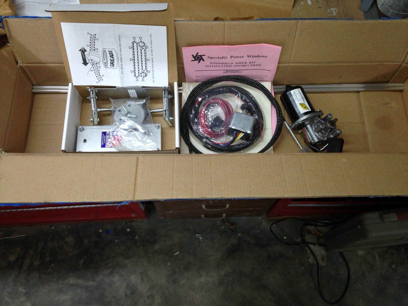 |
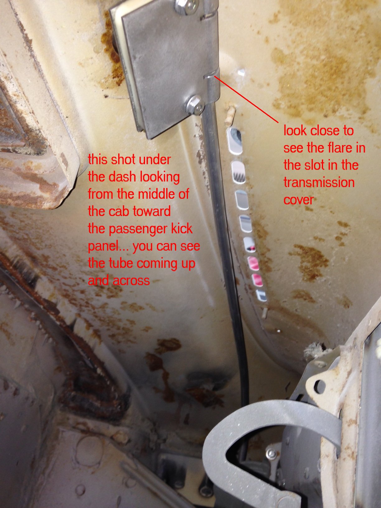
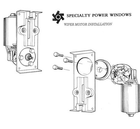
This kit is different from the stock wiper units as the motor is mounted in the kick panel of the cab and operates the wipers thru a 'cable' that runs up the kick panel and across the dash. It actuates two 'transmissions' that contain the pivots for the windshield wiper arms. The cable slides thru a aluminum tube that connects the motor unit to each transmission... they are daisy chained together... no underdash linkage that clicks and clunks or rubs.... or even many moving parts (well not many). |
The first thing I did was read the instructions carefully. They are pretty detailed and have several drawings to help you along. I started by installing the transmissions in the cowl. Well... 5 minutes into the project and I hit the wall. The transmissions in the kit had a 3/8" shaft diameter and my holes in the cowl were 5/8" SPW included a bushing that had to be welded into the cowl, lined up perfectly...square and plumb with the actual windshield and then the transmission shaft would fit in the bushing..... then you did the appropriate body work to pretty it up. My body work was complete and this added a couple of days of body work $$$$. |
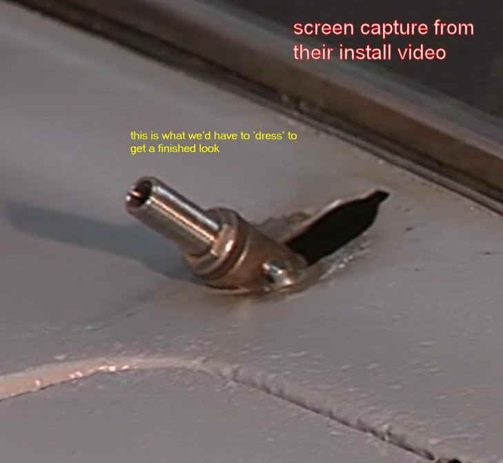 |
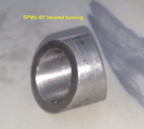
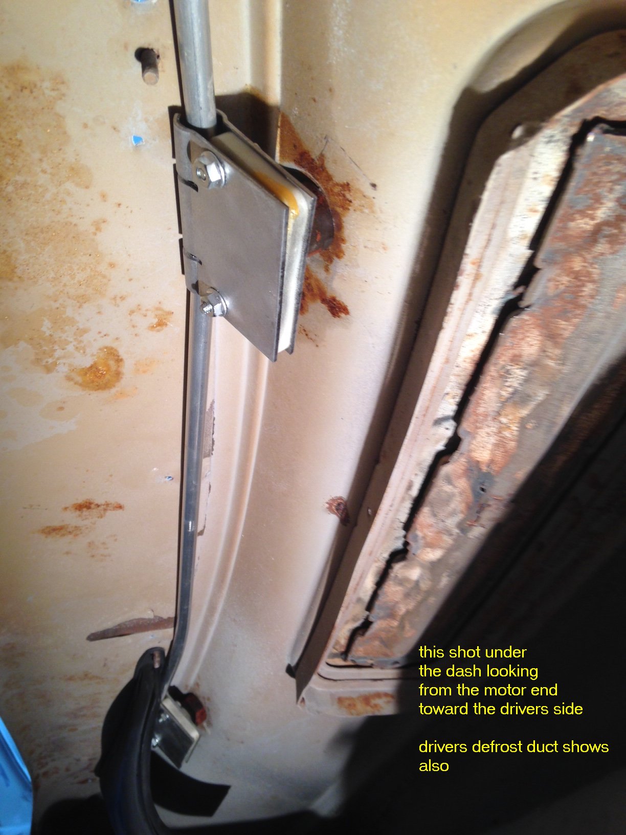
I got on the phone with SPW's tech department and talked to Keith... told him my problem and asked if they had a dress up piece or bezel to cut down on body work. When he asked what vehicle I had and I told him a '53 f-100, he told me they had a seperate transmission that would fit the cowl in that truck... Well... a return of the 3/8" units and a little boot ($60.00) and 3 days later I had the new ones. Why Mid-50 didn't offer that for the trucks they specialize in is beyond me. He included a sloped bushing that was supposed to fit between the transmission and the underside of the cowl... after tinkering with that for a while I found that it wouldn't work (later discovered that it was for a '56, with a different cowl shape) It interfered with the defroster ducts and put the shaft at a wonky angle leaving a gap at the bottom...
|
 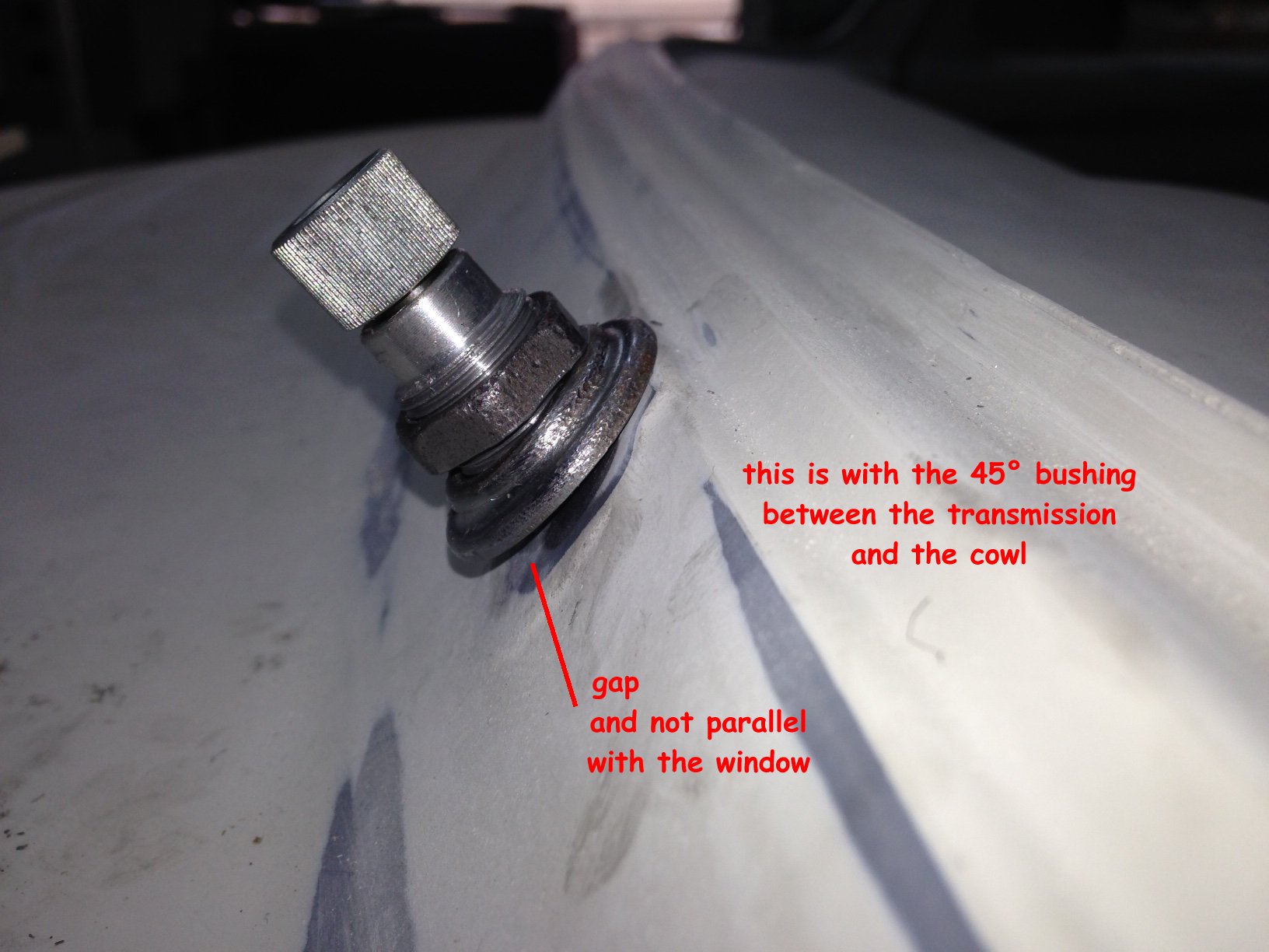 |
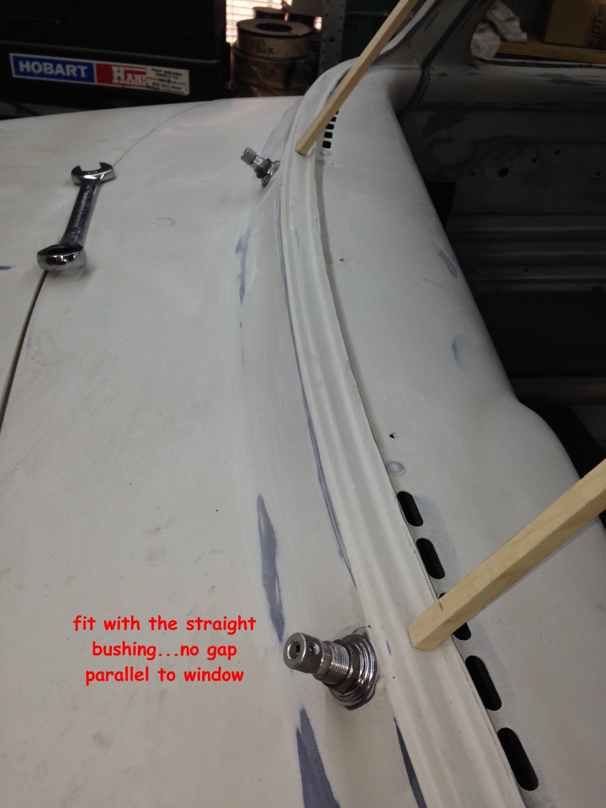
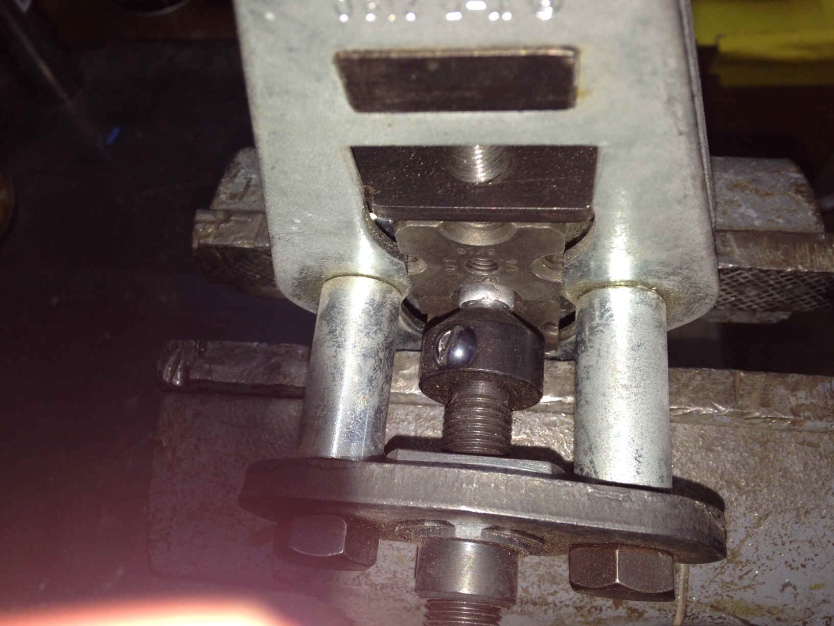
I toyed around with ideas for a few minutes and then cut a straight 3/4" bushing and tried that.... worked out much better,...eliminated the gap and did away with the defrost duct interference. SPW also wants the wiper arm parallel with the window glass... this setup has it within 2-3 degrees. You can see no window here... the square stick simulates the glass for measurement purposes |
 |
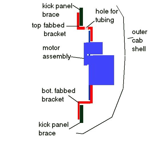
After I was satisfied with the transmission fit I moved to the motor mounting. The motor comes complete ... well, you need to mount the spacer and drive wheel and when that is complete ... installed in the kickpanel. It's covered in the instruction sheet very nicely. They include a flat aluminum mounting bracket that wouldn't work without some modifications... I ended up fabbing up my own due to the way the underdash and kick panel areas are made. Normally you want the kickpanel covered with pretty upholstery in a finished truck, which means you have to inset the motor. a flat mount will not work as the operating part of the motor would be in the cab area. This added a little more difficulty to the install but nothing that couldn't be overcome. I fabricated an upper and lower mount that is 'z' shaped |
 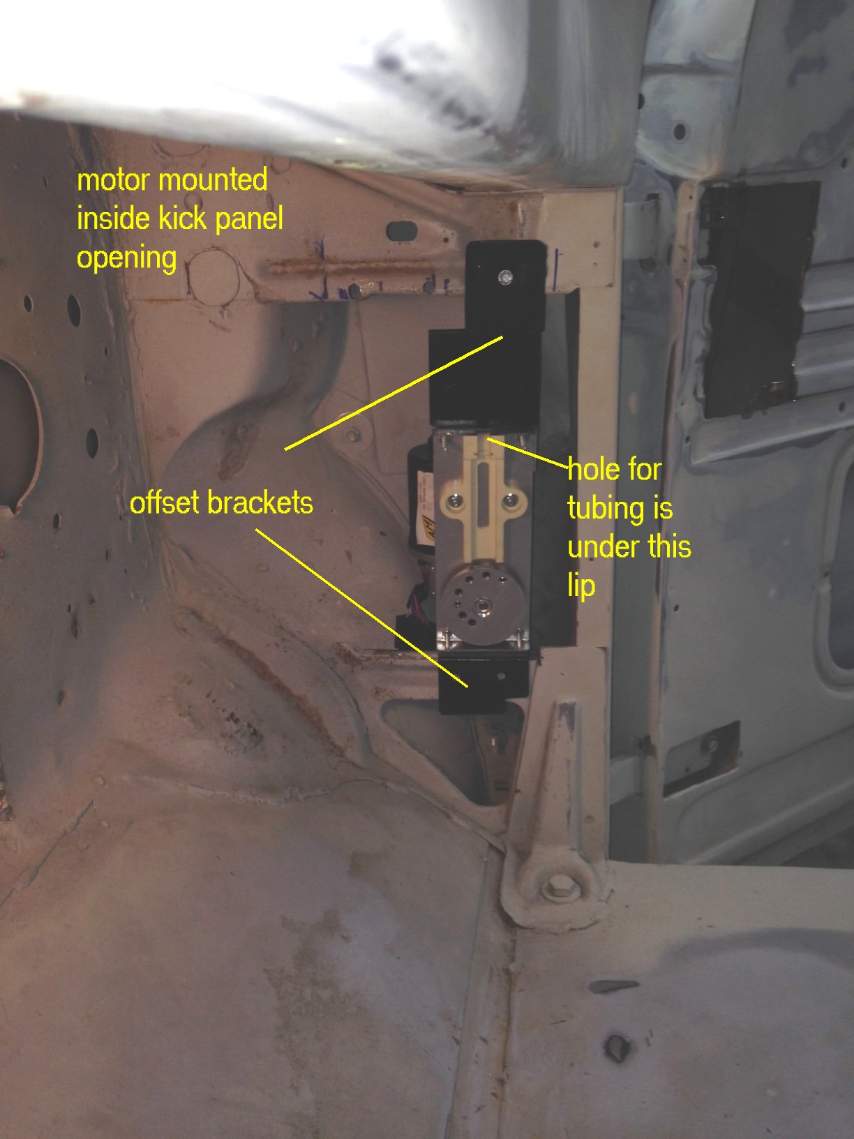  |
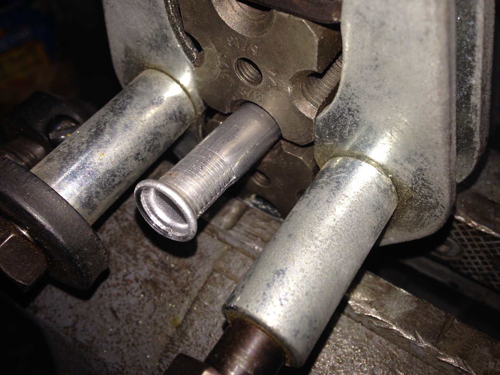
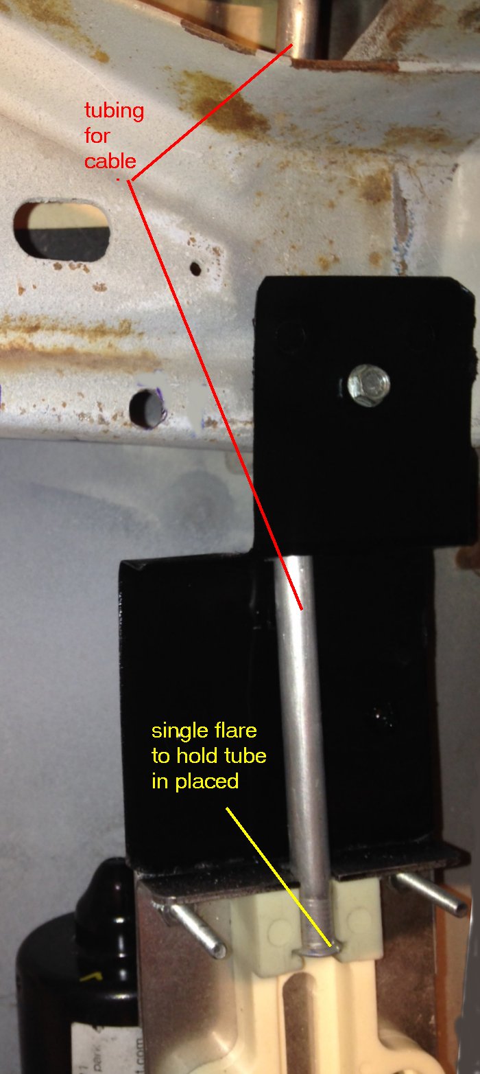
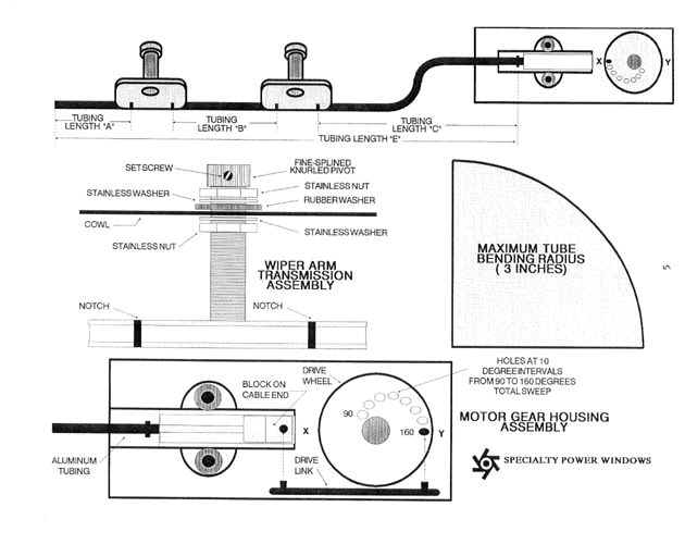
The cable that actuates the transmissions is routed thru aluminum tubing to the transmissions. It leaves the motor and runs up inside the kick panel opening then turns under the dash to each transmission. I mocked up the first piece with a piece of stiff wire to get the length then added about 1/4" to the measurement for the flare. It ended up being 34-1/2". Yours might be different depending on where you mount your motor. Each end of the tubing is single flared to hold it into position at the motor and the transmission |
 |
  |
You need to be careful when forming the curve in the tubing... it can't be less than a 3" radius or the cable won't move through it smoothly. After installing the first tube, measure for the second... mine was 15-1/2' flare to flare... You install them by loosening the nuts on the transmission enough to let them slide in place. |
 |
The last piece of tubing is a stub piece for cable runout past the transmission. Instructions say make this 4" long. I installed this stub and inserted the cable. Slide the cable all the way to the top of the guide block on the motor unit... i.e. to it's longest length. Mark the cable at the end of the stub tube....remove the cable and then cut it with a dremel cut off wheel ( smooth the end leaving no burrs or jagged edges). As you feed the cable, it helps to twist it a little and if it's really tight it helps to turn the wiper pivot nut to ease it along... it will be somewhat tight...that's ok... It will ease up when greased. |
Now, you have the cable out and cut to the proper length... go find some rubber gloves and some wheel bearing grease... and a short acid brush or tooth brush... something to slather on some grease. Have a seat in the floor board with your feet hanging out the door. Grease the cable for about a foot and start feeding it into the tube end on the motor unit. The more grease the better. Now grease another foot... slide it in... continue till there is no more cable to grease. Don't worry about seating it in the slot yet... there's lots more greasing to do. |
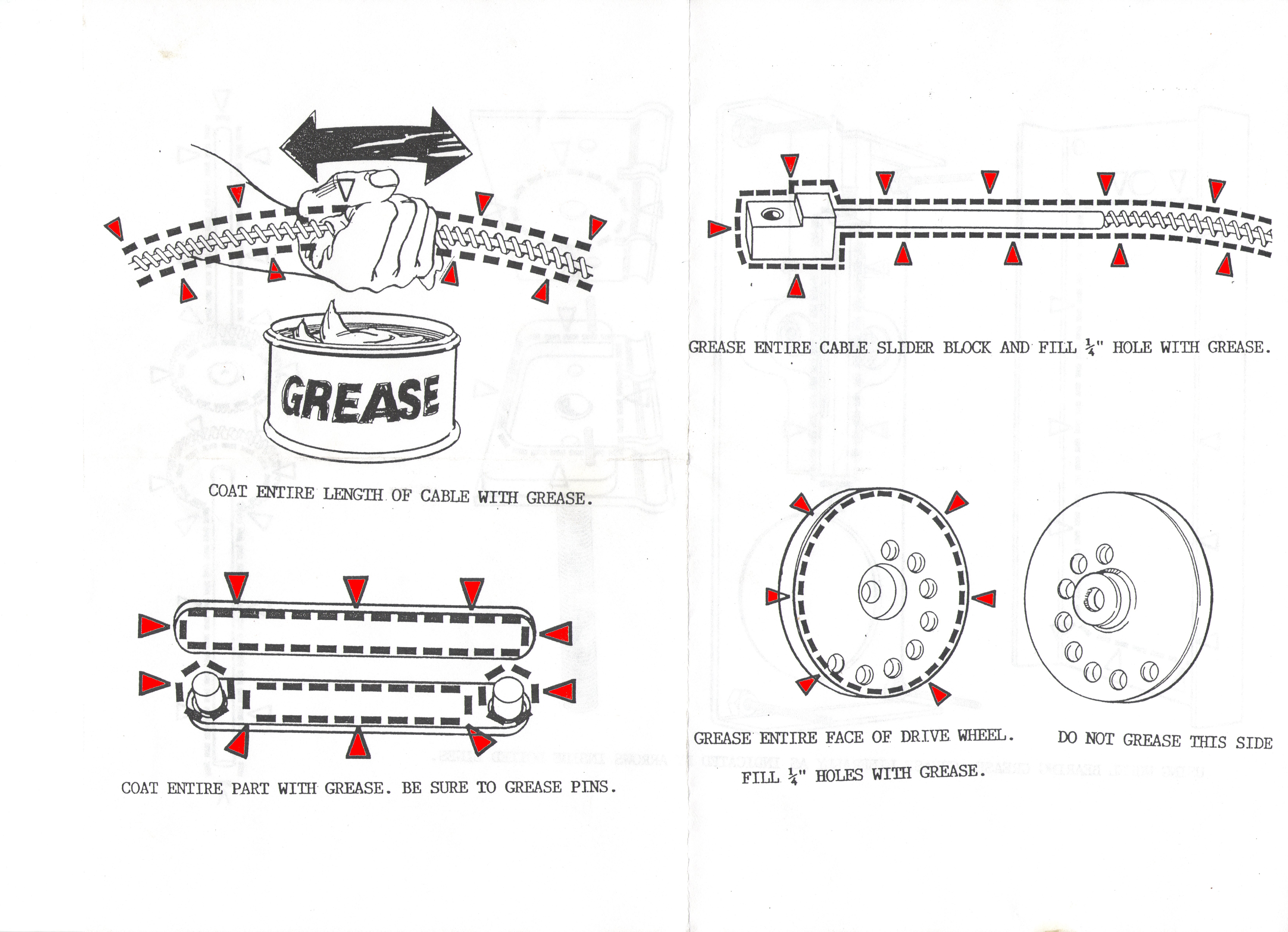
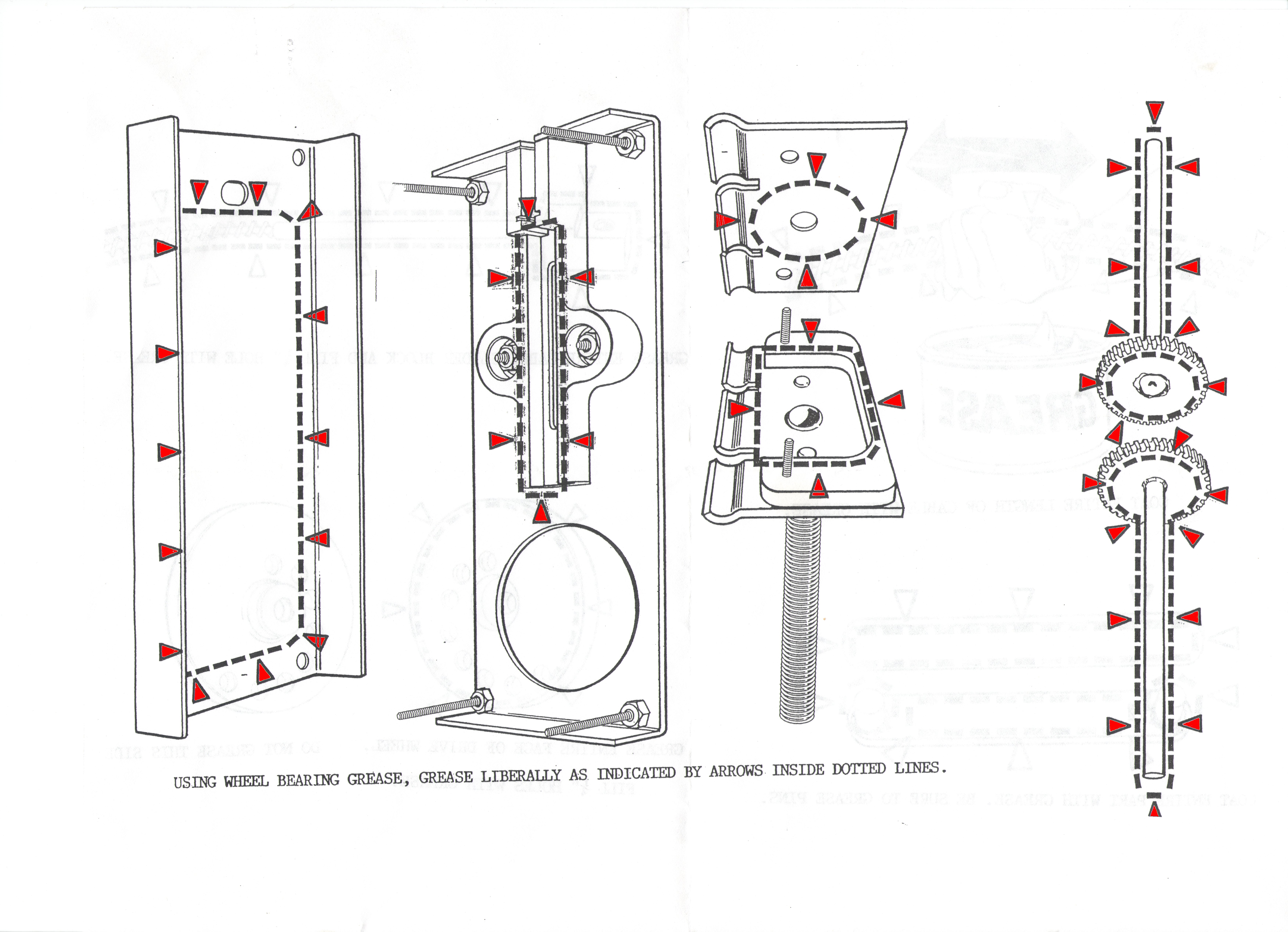
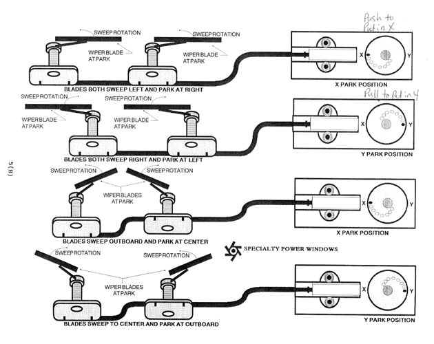
look at the two drawings below.... these are directly from SPW instruction sheet and give better instructions than I can write down... everywhere you see a red arrow or a dotted line... grease the crap out of it, The best way to grease the cable is just grab a handful of grease (in a gloved hand) and work it into the cable as you feed it into the tube. The other parts are easier with a acid brush or small diameter paint brush like artist use... you can get in all the crevises that way. |
 |
 |
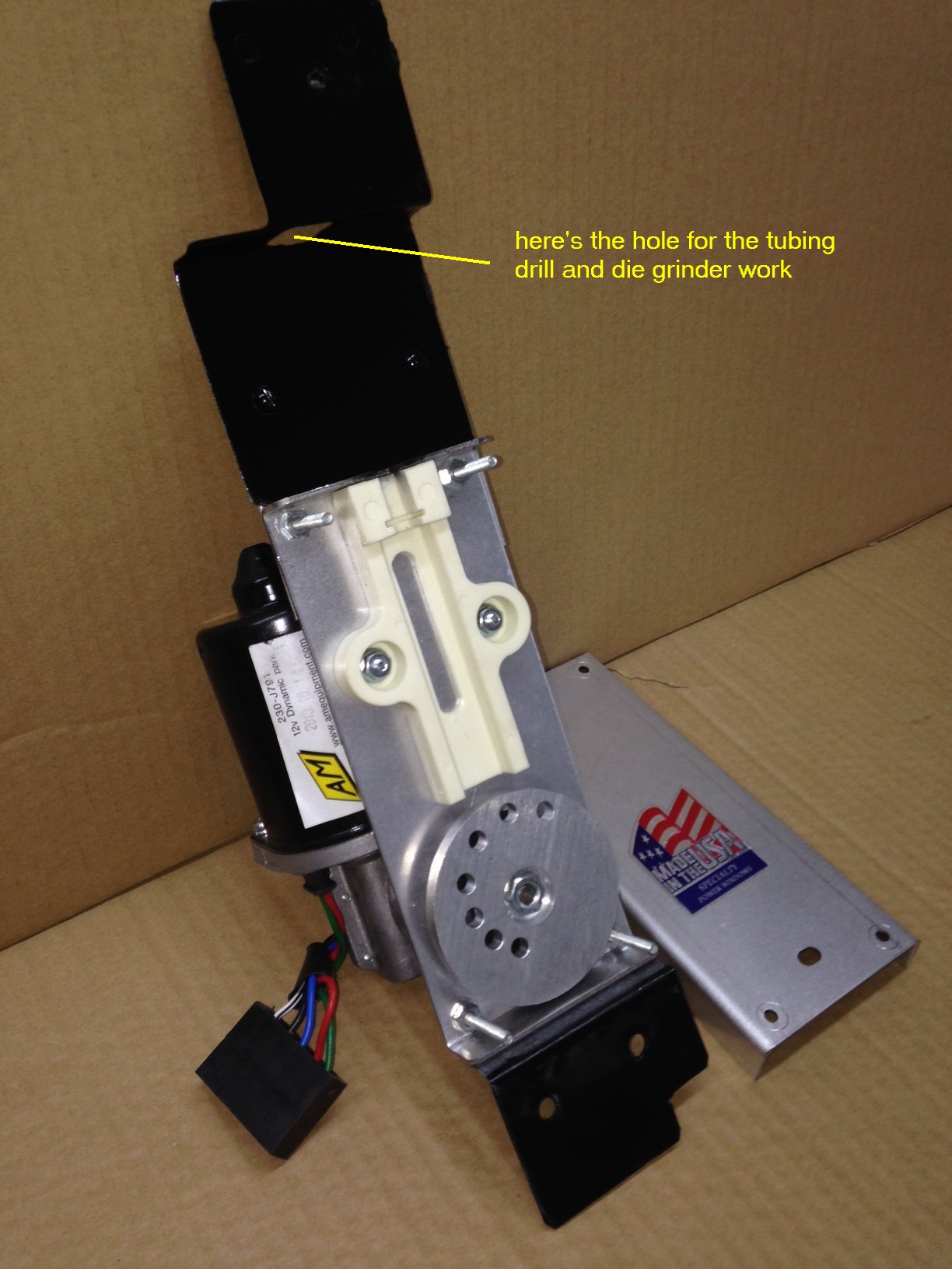
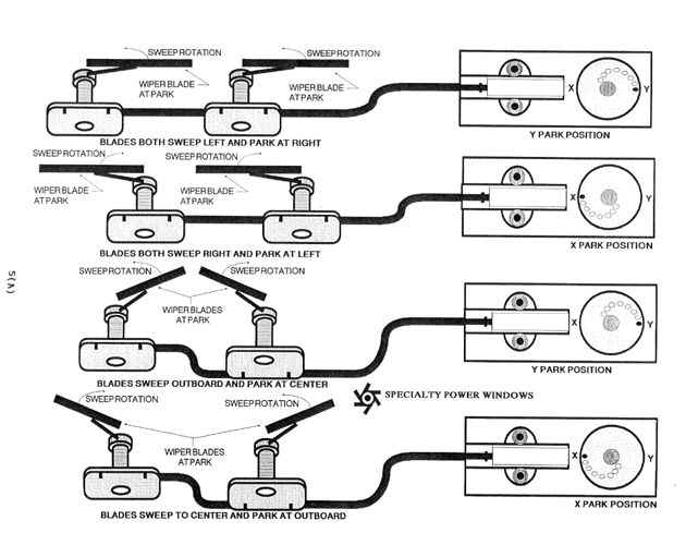
Here's a pic of my motor unit greased up with the drive link inserted into the wheel and to the end of the cable. The placement of the drive link (bar) depends on several things. The instruction sheet shows you which holes to use depending on your direction of sweep, park location and angle of sweep... too much for me to type ..... good directions from SPW...read 'em. But before you insert the drive link into it's proper hold you should cycle the motor to make sure it's in the 'park' position. So, you need to do the wiring next. |
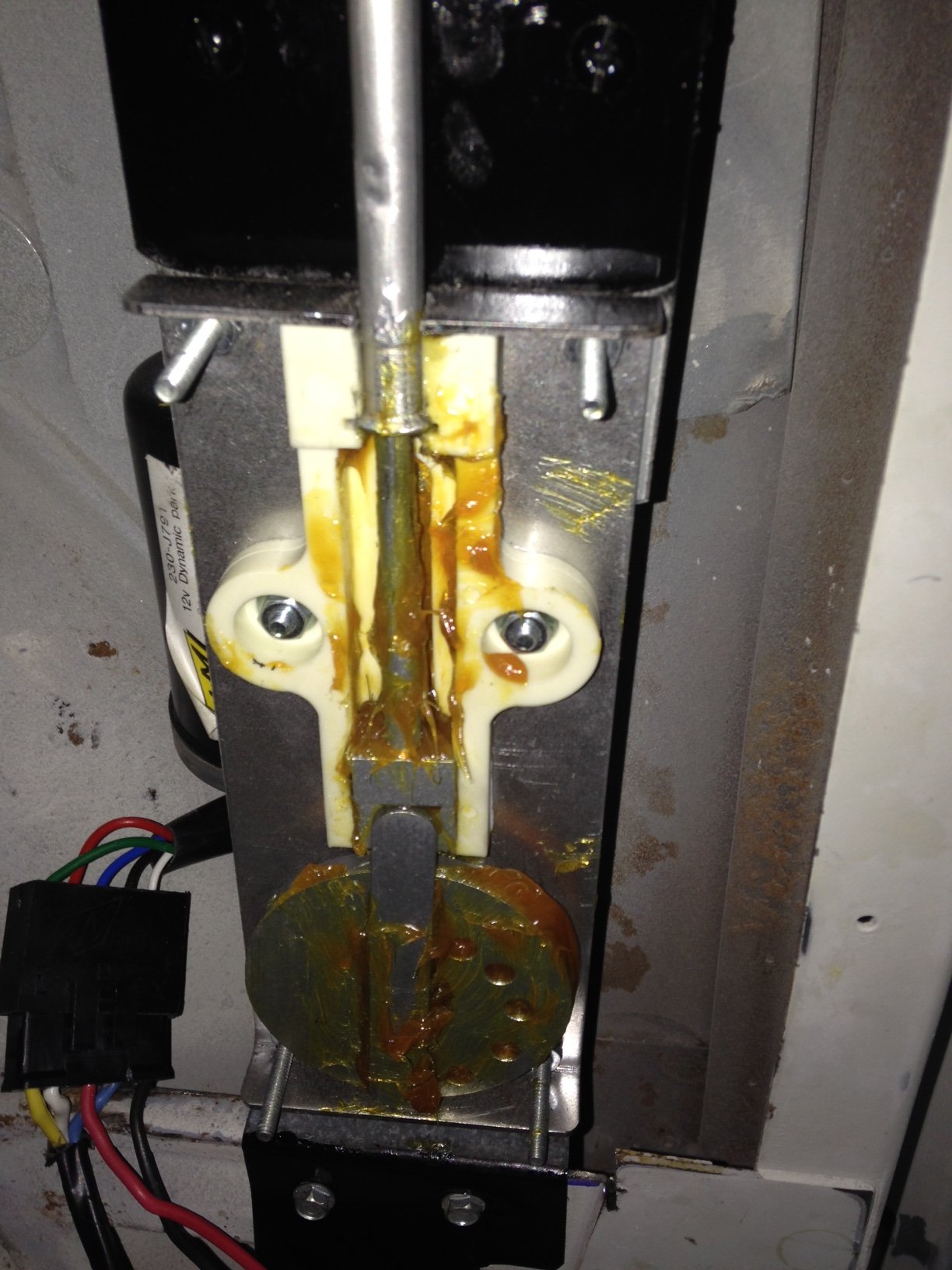 |
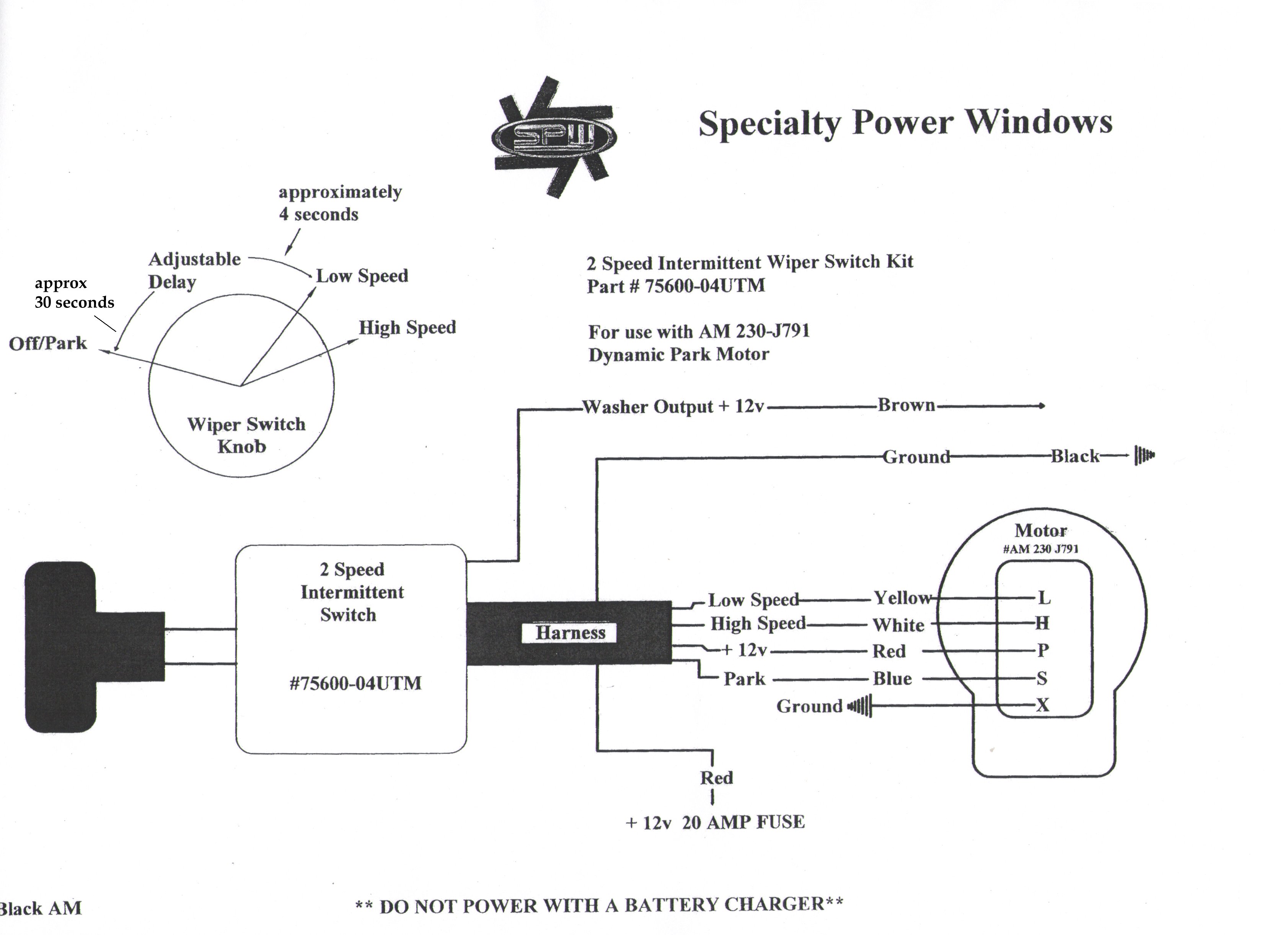
At this point your install is almost done.... except for the wiring, test run and cover install. We'll start with the wiring for the test run. The wiring harness comes complete with switch attached, but the bare wire ends need to have connectors added for the plug at the motor. I'm not ready for final install of the switch yet so I just stripped the wires at their ends and added the terminals. I soldered the terminals to the wire and inserted them into the cable connector. They will fit either way but only one way will hold the connector into the plug... After I soldered and inserted the wires according to the wiring diagram (seen below) I then plugged the connector into the motor connector. You can see that in the picture above. |
Testing the unit is pretty straight forward... one caution DON'T USE A BATTERY CHARGER FOR THE TESTING.. they make that statement quite adamently. Use a 12 volt car battery or a jumper battery pack... guess chargers give you a unregulated voltage. Turn the wiper switch to off. (full counterclockwise). Wire the red and black wires to the battery (two each) and turn the switch clockwise. You can see the layout of the switch below... the first quarter of the full turn if for intermittent sweep, then low speed, then high speed is full clockwise. I choose to just turn enough to make an intermittent sweep then back off, that parked the motor. Now knowing it's in park position you can choose the correct hole in the wheel to insert the link bar AND install your wiper arms and blades in their park position. Determining the sweep angle, park position, etc is well detailed on the instruction sheet... here's the promised wiring diagram. I didn't have windshield installed OR wiper arms and blades yet, so I just watched the position of the knurled post at the wiper pivot point. |
 |
When you are satisfied with the sweep action and park positions you can consider your test complete and successful. If not, do your adjusting on wiper arms or on the link rod and motor drive wheel. One item... when you are testing the wiping action without the cover on the unit, the link bar can come out and make you think you screwed up... if you aren't watching... you might want to hold a finger on it while it's cycling. Happy ?? install the cover with the four screws (don't forget greasing the inside of the cover. |
Below is a scanned copy of the instruction sheets...8 pages. I was very pleased with the kit and SPW tech support... I think you will be too. |
  |
 |
 |
 |
 |
 |
 |
| Boilerplate
denial of liability statement… i.e. the fine print
This project is detailing how I installed the Specialty Power Window windshield wiper kit. There were instructions included but some things just weren't covered.. My ideas and work are just that., it is not patented, engineered or even perfect… it is what it is, a home made project. I’m sure there are alternatives to this design, some even better/cheaper/easier, I just didn’t think of them or warrant them necessary... there are several similar ideas on the internet waiting behind Google for you to see/copy/build…(just like I did) This work was done by me and for me or by friends who were nice enough to help me out. I only ask that if you reproduce it give me credit for it and if you make money from it… give me my percentage. Since I have no way of knowing your level of competence, welding or cutting skills, mechanical ability or estimated intelligence, there are no guaranties or warranties either verbal, written or implied with this article. Along with this article I am giving you absolutely free of charge…that’s right ! FREE !!...the liability, total and complete liability for the use or misuse of this idea will be yours and yours alone. It belongs to you with that in mind… I am in no way responsible for any damage, injury or embarrassment you may suffer from the use or misuse of this homemade thing or installation detail. If it doesn’t look like something you’d be comfortable using… don’t build/use it. If you’re not intelligent enough to make that decision about your comfort level… ask a family member or friend.. but here’s a hint… if you have to ask someone… don’t build it ! Pictures were made at different stages of construction and all assemblies in pictures may not be complete in each shot. I.e.. a picture showing ‘some parts’ only means that it was not finished, but I’ve tried to make the idea complete to the best of my ability. If you have questions or see mistakes or problems, let me know by e-mail and I’ll make the corrections if possible.. Use these ideas at your own risk. Modify them at your discretion and to suit your purpose. Your mileage may vary, batteries not included, much assembly required... wait one hour after building to enter the water, additional charges may apply. not all applicants will qualify for advertised A.P.R., for ages 10 to adult…side effects are comparable to placebos. Do not take drugs when building or operating machinery. JUST SAY NO. Copyright . 2016 John Niolon, All International Rights Reserved. This document may not be copied or published without prior written consent of the author- jniolon@att.net |