| Fifty years of abuse rendered the old stock latches totally
useless. The choice was to go with new stock latches or something a little more modern.
New outside handles/buttons and new striker plates will run you in the neighborhood of
$150.00. Somewhat less if you have some working pieces. Solenoids and bear claw latches
will probably be in that neighborhood, depending on the brand and type of solenoid…
(gear motor vrs pull type solenoids). The latches are generally the same, some a little
heavier duty than others. |
| Since I wanted to shave the door handles and locks, I opted
for the solenoid/bear claw route. Of course it goes without saying that the holes for the
outside latches and key lock must be filled in and prettied up. So I’m beginning with
the bare door after the body work is done. You must also have your doors hung correctly on
good hinges with no slop. So before you start hacking up the doors.. rebuild your
hinges… hang your doors with new hardware and align them just like a final fit. If
possible have the weather stripping installed, although sometimes this isn’t possible
since you haven’t painted the jambs yet. The weather stripping is usually a put it on
and leave it type item. It’s too expensive to put on and tear up taking it off. The
gorilla snot adhesive doesn’t give up easily without tearing up the strip. |
| I purchased my equipment from StreetWorks. Other
dealers sell them…check the catalogs. From what I have been told, the heavy duty
solenoids with a gazillion pounds of pull are not necessary in any but the extreme cases
where old, worn stiff latches are being used. The bear claw latches need very little pull
to open them. The screw motor actuators have plenty of torque. |
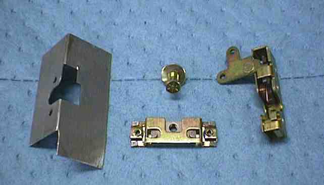
| I bought two Spal screw motor actuators, two latch mounting
plates…. Two bear claw latches… two latch posts and two adjustable mounts (cage
nuts) for the latch posts. |
|
| parts needed for one
door (less actuator) |
|
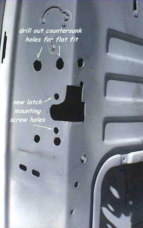
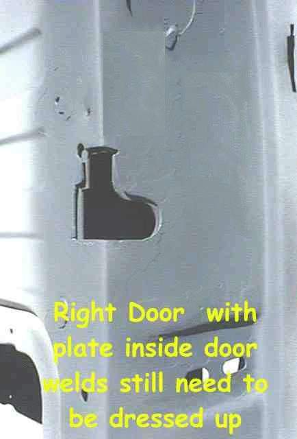
| I started by holding the latch mounting plate up against the
outside of the door and scribing the latch hole on the corner of the door. I chose to
mount the mounting plate on the inside of the door so the cuts will be a little deeper,
but this will give you a starting place and you can file or grind the rest after you get
started. My new latches were mounted lower in the door than the stock latches so I would
have some nice flat surfaces to work with… the original striker bolt holes and the
latch holes will be filled and dressed smooth. If you use your mounting plate on the
inside of the door as we did, there are probably two or three countersunk screw holes (old
latch mounting holes) that must be drilled or ground out so the plate can mount flush.
These can be used for the rosette welds that hold the plate in place. I welded mine on the
latch face of the door and on the inside face of the door. |
|
|
 |
| The latch mechanism is held to the mounting plate by hex drive
button head screws so the holes for these screws must be drilled through the door facing
so the latches can be removed later if necessary. Locating these holes is easy using
a set of calipers and transferring the center of hole from the inside of the door
face to the outside. Drill them large enough to pass the screw.
The
next step is to locate the position for the latch post in the cab door facing. Mark the
position of the latch cutout in the door on the cab door facing and measure the distance
from the inside door edge to the center of the latch mechanism with the latch closed. This
will be your ‘set in’ distance for the post. Keep in mind… if you
don’t have your weather striping installed yet, this dimension might need some
adjustment later. Using the adjustable mounts, you can easily move 1/4 to 1/2 inch in any
direction. |
| |
| Mounting the solenoids / actuators |
|
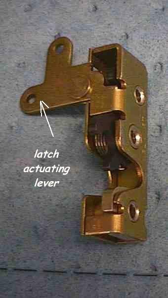
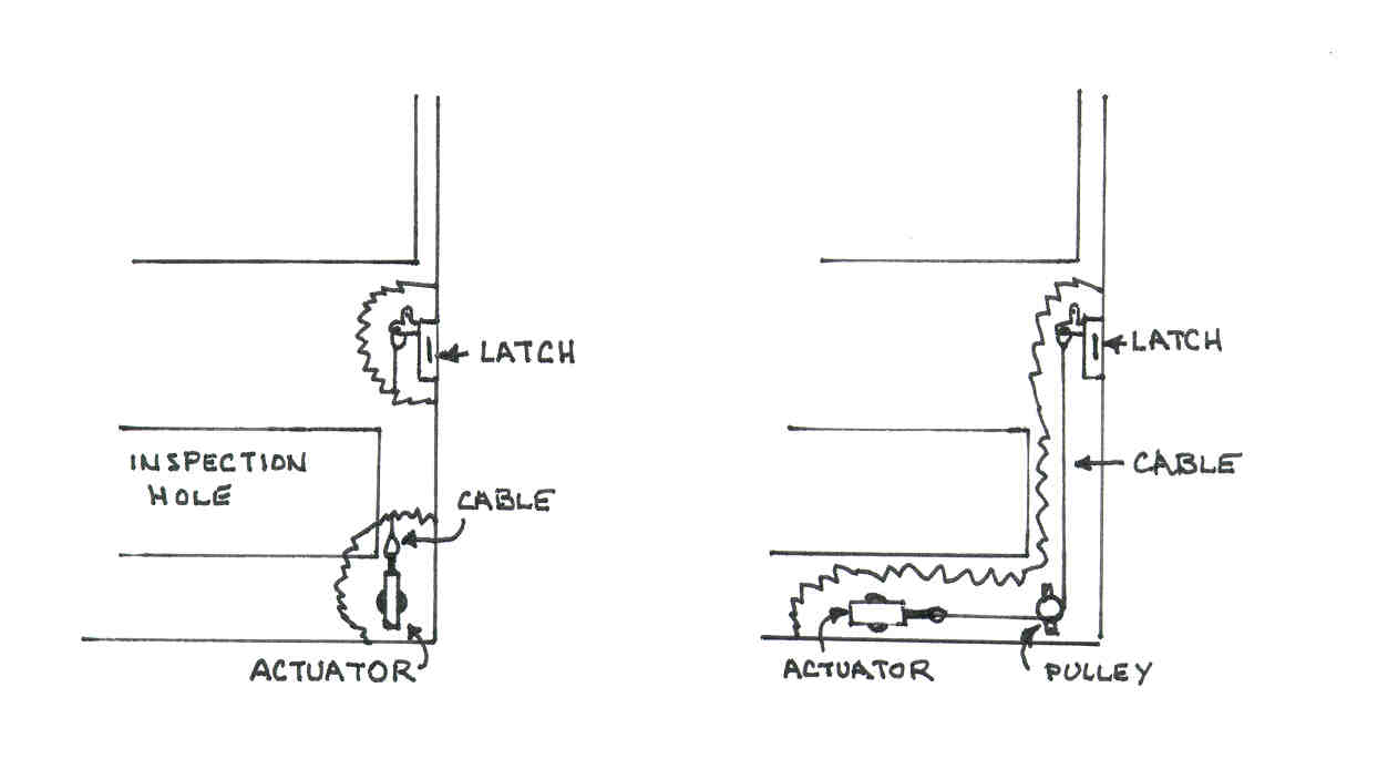
| Looking at the bear claw latch you can see
that there is a lever extending from the top of the latch with two holes. This is the
actuating lever for the latch. Pulling down on the lever releases the latch to open. The actuator or solenoids operate with a
pull motion…usually about 3/4" to one inch. This is gracious plenty to actuate
the latches. Normally the actuators are located in the lower portion of the door in order
to clear the window and associated window hardware/tracks/mechanisms. The easiest mounting
is with the actuator mounted vertically and pulling straight down on the lever in the
latch. Sometimes in some type doors, this isn’t possible and the actuator must be
mounted horizontally. If this is the case, the retailers offer a kit (or you can scrounge
up the parts) with a cable and pulley assembly that will allow the actuator to work
"around the corner" or at 90 degrees to the latch lever. |
|
 |
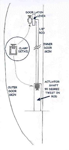
| In the large Ford truck doors there is
plenty of room for a vertical mount. First determine the proper position for the actuator.
I measured the distance from the door latch face to the center of the hole in the latch
lever as 2 -1/4 ". This is a little cumbersome, reaching through the inspection hole
of the door… holding the ruler between the latch lever and the door facing and
looking down through the window slot to read the distance. Having a helper here is
great…especially if your arms are a little short. I scribed a mark on the inside door
facing 2-1/4" from the edge then using the actuator for a pattern, I lined up the
center line of the actuator shaft on the scribed line and marked the two mounting holes on
the outside of the door. Drill
the two holes…. And making sure that the actuator is turned so the center line of the
shaft is over the scribed line… mount the actuator loosely to the door. Now…
another cumbersome measurement. Reaching back through the inspection hole, measure the
distance from the hole in the latch lever to the hole in the actuator shaft. Your
connecting hardware has to be that length. Mine was 14-1/2".
There are several methods for
connecting the two. The actuators come with a flat drilled bar, a rod and some strange
hardware. I played with this and was never satisfied with the fit… it was sloppy.
You can use light gauge cable with
cable clamps. This is easy to install and adjust to remove the slack. I finally settled on
a straight 1/8" steel rod with a 90 degree bend on each end.
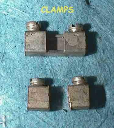
I fabricated a set
of clamps from some old electronic terminal strips which are nothing but a piece of
3/16" square tubing with a set screw that clamps the rod in the tube. Before I
install the latch in the door I installed the rod on the latch actuator lever and attached
the clamp. Then installed the latch in the door… slipped the rod through the actuator
shaft and added the clamp… simple, clean and no slop in the movement. Be sure to
leave a little space between the levers and actuator shafts and the clamps. You don’t
want the assembly tight enough that it binds or the actuator sticks in the
‘pulled’ position instead of returning to the top. Another problem… be sure
that the end of the rod faces the outside door skin (on the latch end) it’s a tight
squeeze between the latch and the inside door frame and it could hang or bind up there. |
|
 |
|
|
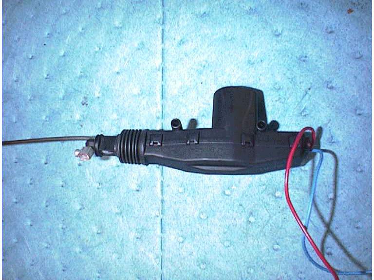
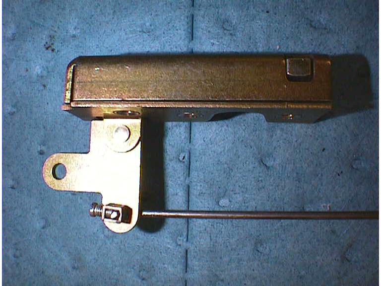
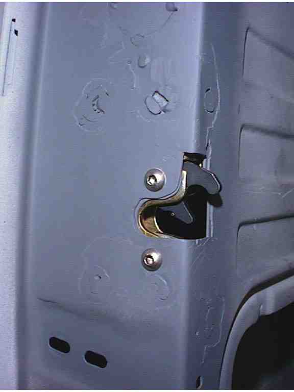
| Below are
some related pictures... the solonoid with the rod attached, the bear claw latch with rod
attached, the whole assembly out of the door and the installed latch mechanism. The
only other part needed to complete the installation is mounting the post that the latch
grabs into the cab post. I haven't done that yet and probably won't until I install
the weather stripping. I want to get a good fit and I don't want to install the
weather stripping until the cab is painted.
|
 |
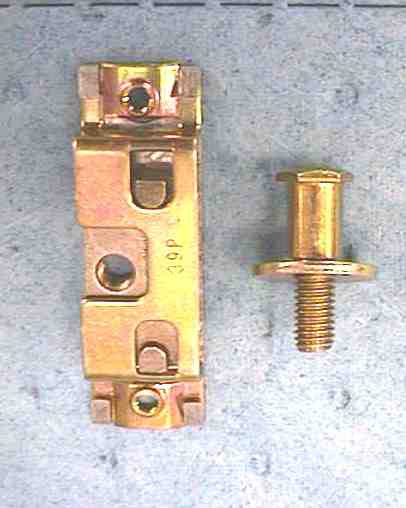
| It's a
simple matter to line up the door with the seams evenly spaced, then from inside the cab
you can make the proper marks to center the post in the latch opening. The latch
post hardware has a captive nut in the holder and allows for about a 1/4 - 1/2 inch
adjustment in each direction. Once you've found the center of the latch opening, you
merely drill the hole through the cab post... install the post mount bracket and screw in
the post. Of course, the post mounting hole should be large enough to allow for that
adjustment that will probably be needed.. |
 |
| When that part is completed on my truck, I'll update this
article with pictures... good luck with your project |