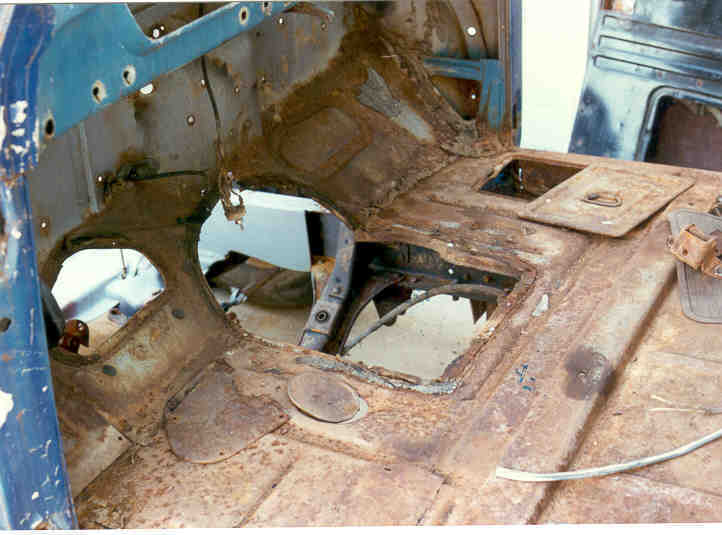
| After I drug my beauty home and rolled it off the trailer I started my survey. At first glance the floorboards looked pretty sound. After I removed the seats and scrapped off the rubber mats, it looked worse than before but still not too bad. After I soda blasted the complete cab I realized I had a sieve for floorboards. I was surprised I hadn't stepped through them already. One thing rubber mats are good for is holding moisture and promoting rust. Years of abuse and a half inch of crud in the floors compounded the problem. No doubt they would have to be replaced.
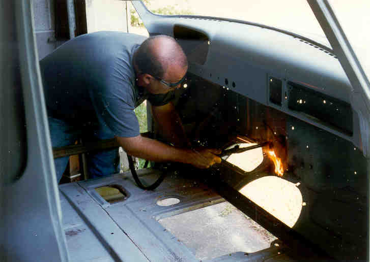
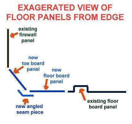
The floors are reasonably flat and can be divided into three major sections. #1 -The sloped toe board section that starts at the bottom of the firewall and extends down at an angle to the main flat floorboard. #2 - the front portion of the flat part that has the transmission inspection/access hole in it and #3 - the rear flat portion where the seat is bolted on. After poking around with a sharp awl, we decided that sections one and two had to go. The section beneath the seat was still nice and sound and would make a good transition point for the added sections. The seat has a raised rib across the width of the truck which strengthens it and cuts down on the 'oil can' effect of a large expanse of flat metal. We decided to use 14 gauge material (.0767") for the floor panels. It's a little thicker than the original floors, but it will add a little strength to the floor but mostly it was what was readily available. The plan was to use two separate pieces for the toe board and the floorboard with a angled joint piece where the two came together. The angled seam piece was approx. 3 inches high and as wide as the cab and bent to the original angle (approx. 135°) We began by cutting out the toe board section first ( this isn't my beautiful head..but the hairline is the same)
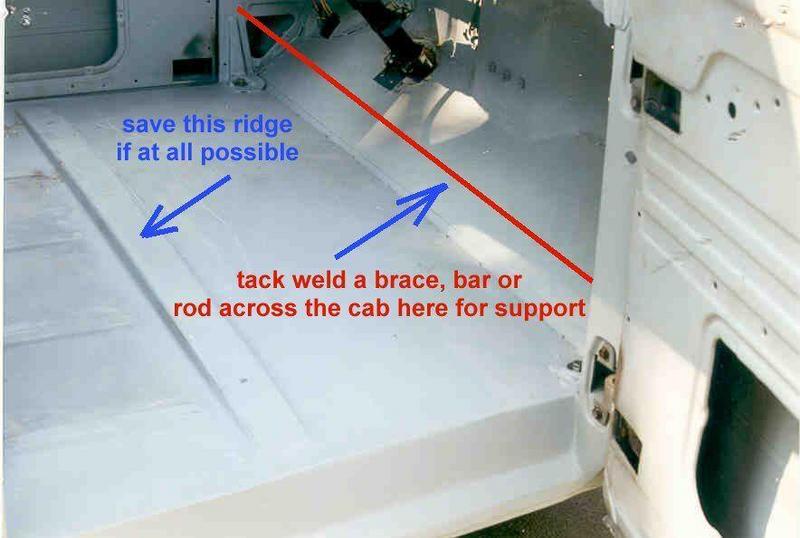
The next step was to cut out the floor section, but we were concerned with the cab spreading so before we did the cut we added a brace between the cab sides to prevent it from spreading. Unfortunately the one-hour processor ate my film with these pictures, so I didn't get pictures of these steps. A sketch will have to do here.
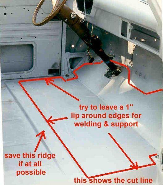
We torch cut the area shown in the picture below and left a 1" lip around the perimeter for support and to give us a clean edge to weld against. It's hard to see in this picture but the sloped panel and the flat panel are joined at their joint with a angled seam piece. It will be apparent in further pictures when we cut the transmission hole. We decided to cut around the cab mount pointsŠthe metal there was still in good shape and it would only make the job more difficult. Your mileage may vary here.༯p>
After the old metal was cut away, the new pieces were held in place and marked for trimming, then tack welded in place. The final trimming was done and the panels were stitch welded in place. We used roughly a 3 on 3 weld (3" of weld every 3") the seams will be filled with seam sealer (silicon, body seam sealťtc) for water proofing and protection. We used the angled seam joint piece for convenience but it also adds some structural strength to the floor panels. The double thickness there stiffens up the floor and cuts down on that "Oil Can" effect. It was first tack welded to the flat panel which was tacked into the cab, then the sloped panel was set into the angled piece and tacked in. It gave us a third hand to hold everything together.
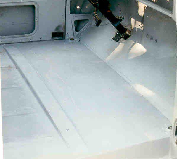
After the final fitting and grinding was done we cut out the brace inside the cab and sprayed a coat of primer on both sidesŠhere's what the final product looked like.
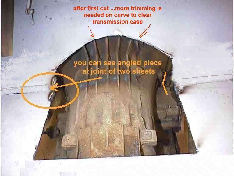
Of course all of this has to be done with the engine/transmission out of the vehicle, or at least it's easier that way. You could make your cuts for the transmission hole before installing the panels but it's much more difficult fitting, grinding, etc. Another option would be to jack up the cab above the transmission and do the workųtill more work. My truck was being done frame up so the engine and transmission were not in the way. Eventually you will have to install the engine and transmission to make the cuts and I decided to remove the front cab bolts and jack up the front of the cab. Then the engine and transmission were installed and the transmission hole cut was measured and transferred to the floor boards. We found the widest part of the transmission, added an inch to each side and drilled through the floorboard at that point. Then from the top.. using a framing square we squared up a hole and marked it on the floorboard. The toe board cut was a little more complicated since it wasn't square and had to be cut around the bell housing. With some preliminary measurements I made a "first cut" mark, knowing some trimming would have to be made. We drug out the plasma cutter and made the main cuts in the floor board and the preliminary cuts in the toe board. After doing this and dropping the cab..checking clearances,cutting again, checking again, finally we came up with the final fit.
I plan to use a metal transmission cover offered by Mid-50's F-100 instead of trying to roll/bend one of my own. Theirs is preformed and looks very nice.. It also accidentally (and incidentally) fit my hole !! That's about the whole thing. It's not a terribly complicated project. A plasma cutter would have made the removal a little quicker and a wire welder makes the welding easier than stick welding.. If you need access for master cylinder filling for an under cab booster, then other holes need to be cut in the floor and access panels made. If the rear portion (under the seat) needs replacing I'd stress using adequate bracing inside the cab so the bottom does not spread and distort the shape of the cab and really make a mess of your cab mounting points. You probably won't notice it until you have the panels welded in and place the cab and then the repair would be more than any of want to tackle.
While this was done on a '53 f-100 the same procedure would apply for any model.ࠐretty rolled patch panels are available from several aftermarket souces and they aren't that expensive, but they ain't gonna show in my truck and free available 14 gauge was a better 'fit' for my wallet. If you are doing this on a running vehicle, I guess I should caution you on brake lines, fuel lines, wiring,....etc. and a cutting torch or plasma cutter...They don't usually discriminate between floor pan and fuel line. good luck. Copyright 2001 John Niolon, All International Rights Reserved. This document may not be copied or published without prior written consent of the author. This work was done by me and for me. I only ask that if you reproduce it give me credit for it and if you make money from itŊgive me my percentage. Since I have no way of knowng your level of competence, welding or cutting skills or mechanical ability...There are no guaranties or warranties either verbal, written or implied with this article. Pictures were made at different stages of construction and all parts in pictures may not be complete in each shot. (I.e.. axle shown as one piece in certain shots only means that the axle assembly was not finished) but I'e tried to make the plans or drawings complete to the best of my ability. If you have questions or see mistakes or problems, let me know by e-mail and I'l make the corrections if possible.. Use these ideas at your own risk. Modify them at your discretion and to suit your purpose. Your mileage may vary... batteries not included... much assembly required... wait one hour after building to enter the water...additional charges may apply... not all applicants will qualify for advertised A.P.R...for ages 10 to adult... side effects are comparable to placebos... Do not take drugs when building or operating this machinery. Just say NO!!
John Niolon 3700 Virginia Drive Hueytown, Ala 35023 jniolon@att.net |