Well, it's started. Although I'm excited about seeing that new Mustang II crossmember under the frame.. I've been dreading the removal of the Volare Clip. Perhaps a little history is in order here. When I first got my beauty I had been reading everything I could find on modifications for her. One of the favorite suspension choices was the "Volare" clip. Actually it is nearly any Chrysler product that had a bolt in front clip. Everyone I talked to and all I read said that this was a easy, inexpensive way to upgrade from straight axle manual steering to independent front power steering. And, it was true... for about $200.00 I was in business. We fabbed engine and transmission mounts for a 2" offset. We thought there would be ample room with that offset for everything. Everything looked good until I ordered a set of Sanderson ceramic coated headers for my 460. After installing them I only had 3/16" of clearance at the steering box, and that was after trying three different 460 headers on the left side ! I knew that when the engine torqued the headers would bang on the steering box and I really didn't want my $400 + headers banging on anything ! |
|||||
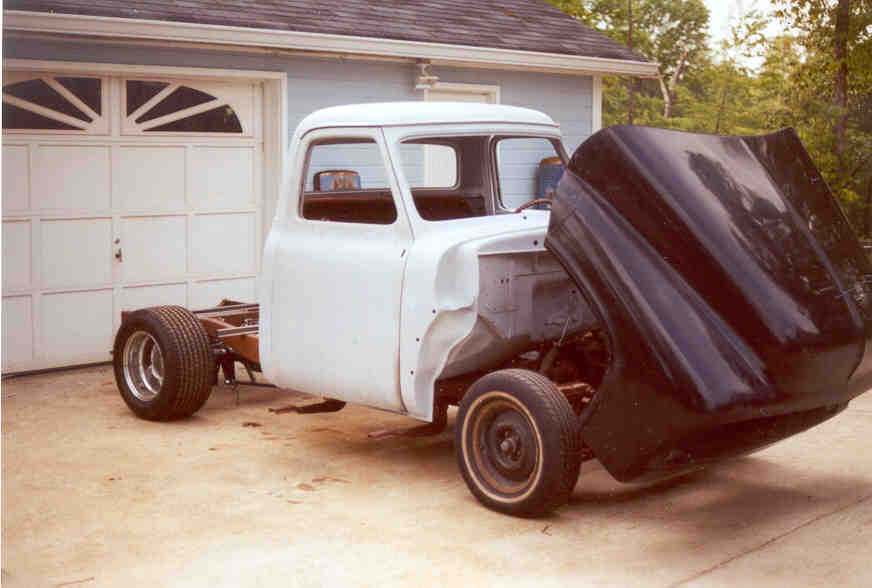
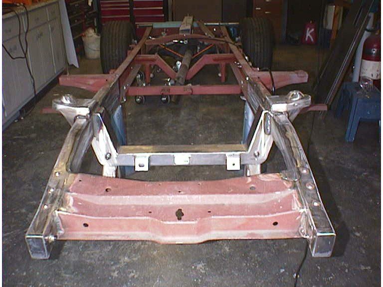
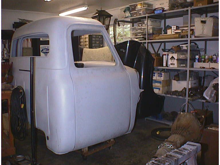
| The truck was already at this point... | |||||
|
|||||
| Cab was installed, steering complete, front tilt operational, all brake and fuel lines run and connected. Engine and transmission had been set and all mounts were complete. All of this had to be removed and set aside or removed to be replaced. One nice Sunday afternoon I did just that. Removed the front flip and set it on the other side of the garage. Using an engine hoist I removed the cab (after disconnecting steering, brakes and master cylinder)and set it on a rolling cart to move it to the other side of the garage also. The engine/transmission was last and it was set on another set of rollers and also pushed to the other side of the garage with everything else... it's getting crowded over there now. | |||||
 |
|||||
| My wife asked me at lunch that day, how long I'd been working on this truck and I really didn't remember. After looking it up I found that it was the seventh anniversary of it's arrival on my place. Seven years... and it took me about 5 hours to back up six of those years to what you see here..... | |||||
 |
|||||
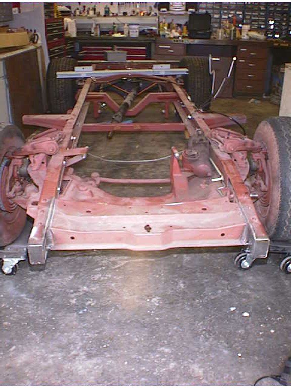
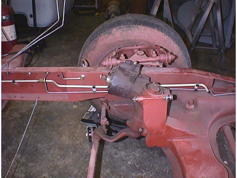
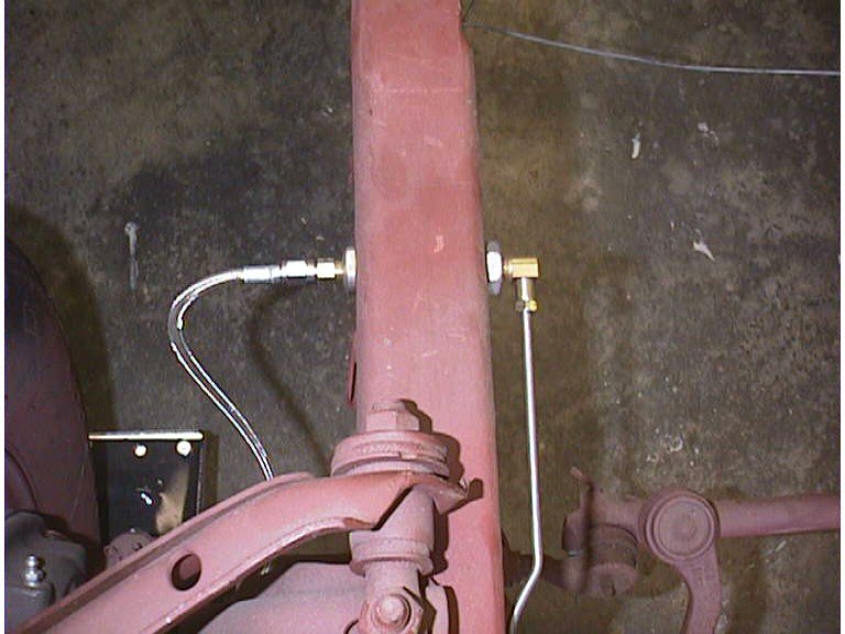
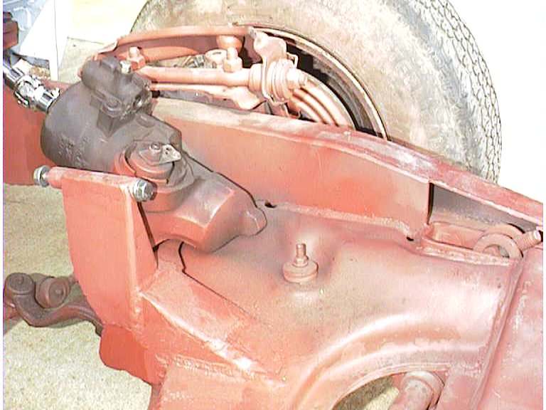
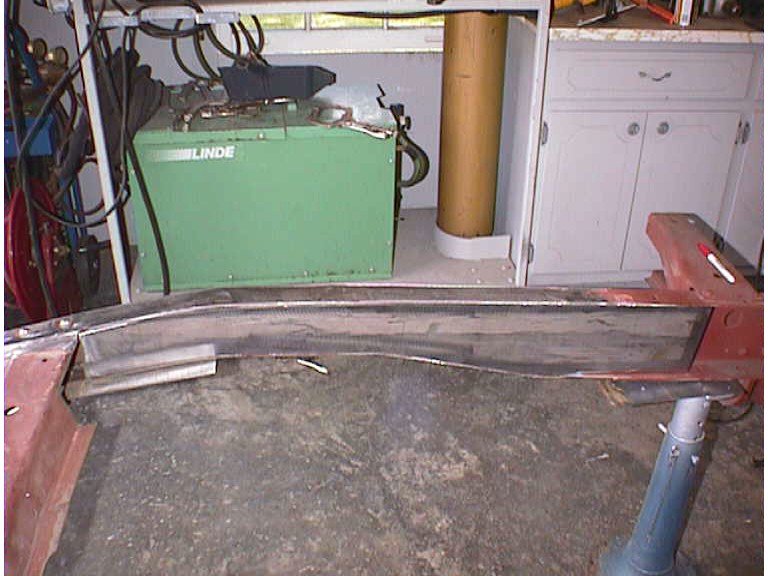
| This was taken before the brake and fuel lines had been removed and the shots below show those lines | |||||
 |
 |
||||
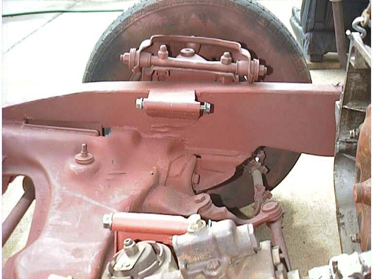
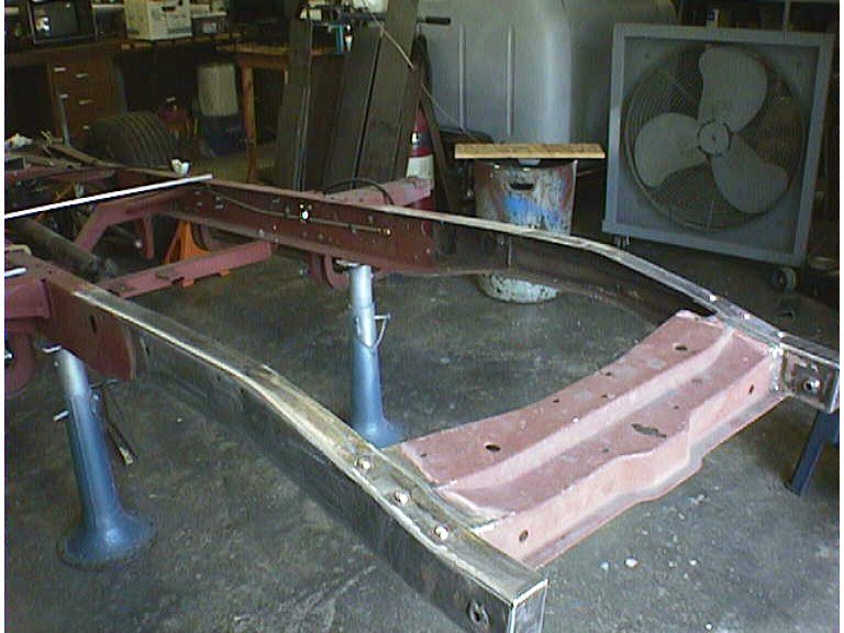
| Our next step is to set it up on jackstands (it's on wheel dollies now) and remove the front suspension components, tires, wheels and upper control arms so we can access as much of the weld as possible. Then with the plasma cutter cut as closely as we can to the subframe. There are places where a torch will have to be used due to lack of space for the plasma gun. We welded the subframe in solid on both frame rails and to the front cross member, so we've got a lot of cutting to do. The boxing plates will have to be removed and replaced after the MII cross member is installed... the old ones will be useless, so that will be another cut around the top of the frame rails. | |||||
 |
 |
||||
| So, now the frame is up on jack stands and stripped of most of the suspension, and all the lines. We're ready to start cutting.. I've transferred the axle centerline to the frame, so we have a reference for the new install. Heidt's uses the front spring shackle hole as it's reference point.. and measures back 19-3/4" to the cross member centerline. Since that portion of the frame was removed to install the volare clip.. we lost the reference. But, the rear spring mount holes are still there and according to the Ford shop manual it is 41" between these points center to center. Some simple math 41-19-3/4=21-1/4" from the center line of the rear spring hanger, should put us at exactly the same place. A quick check from the rear axle center line should give us 111" total wheelbase. The kit moves the wheels forward one inch adding to the original 110" wheelbase. | |||||
Day 2 |
|||||
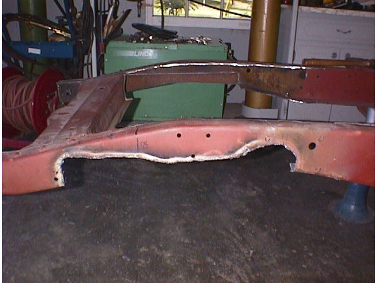
| We've walked around
it a couple of times and we're ready to start the surgical removal of the Volare
clip.. I want to be careful about the cutting, someone might be able to use this
clip and I want all the cuts to be in the frame or boxing plates. We fire up the
compressor, plasma cutter, oxy/actl torch, drag out hammers and prybars and start flailing
and burning. About an hour later the clip (with the aid of a floor jack) slides to
the floor. The frame rails are hacked up pretty well. We had done a very, very
good job putting it in. Funny how the smallest little tack weld can hold so well
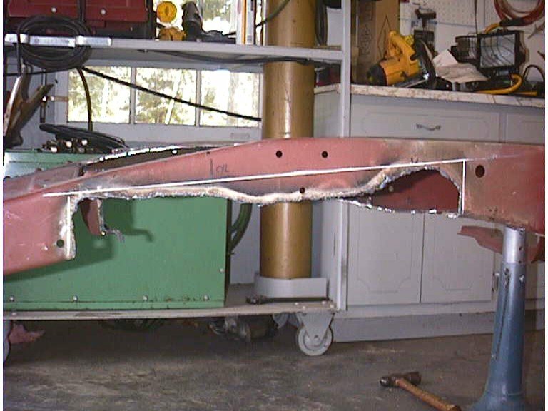
and be so hard to find. The pictures below show the drivers side frame rail after
the removal. Ok, so it's not so surgical, but it ain't there anymore. I've got
to admit I'm a little puckered up about the condition of the frame rails, but Dave assures
me that we can fix it 'as good as new'. If you've never read any of my other
articles you don't know Dave. He is a master fabricator and builder of much sought
after drag cars. His job description at work is a maintenance utilityman. It
means he an expert in electrical, hydraulic, mechanical and piping repairs. If you
can show him or tell him what you want to do... he can do it or build it. He never ceases
to impress me. I am very fortunate to have him helping me with my project...
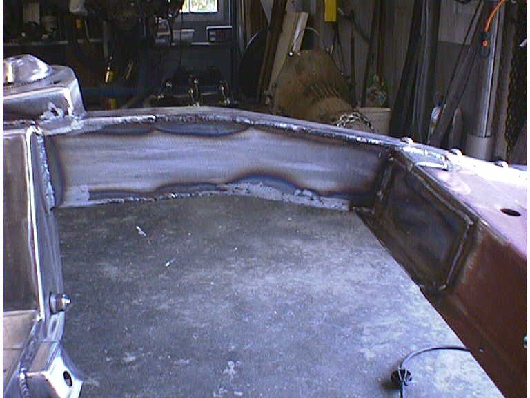
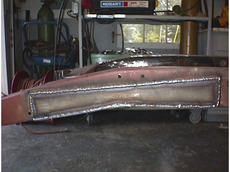
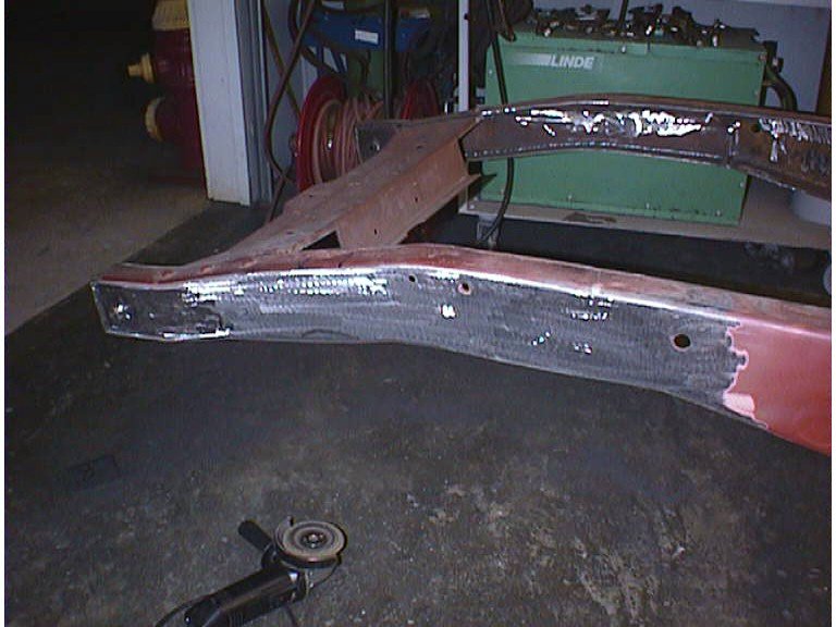
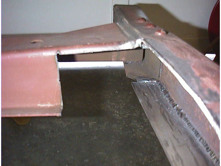
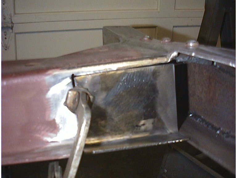
and, I probably owe him the rest of my active life. I'm afraid to ask ! When you look at the picture below, pay no attention to the opposite frame rail.. the picture was taken after we had started putting in the patches. But, if you do look you can see how well the patches are going in the frame. The pictures below show a side view of the cut made to remove the volare clip and a front shot showing the 'gutted' frame rails. The lower pictures show the cuts necessary in the front cross member to remove the Volare clip.. All of these cuts will be patched and invisible when completed. |
|||||
 |
 |
||||
 |
 |
||||
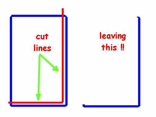
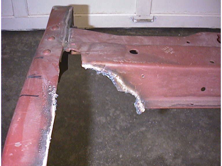
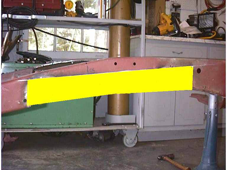
| We mark the frame rails with soap stone to square up the cuts and clamp a piece of angle iron along the cut line. We'll use that angle as a straight edge for the plasma cutter to follow. A few minutes later we have a nice square hole in the frame rail that had once been what you see above. I didn't get a picture of the squared hole... but the second picture shows what you should come up with... | |||||
  |
|||||
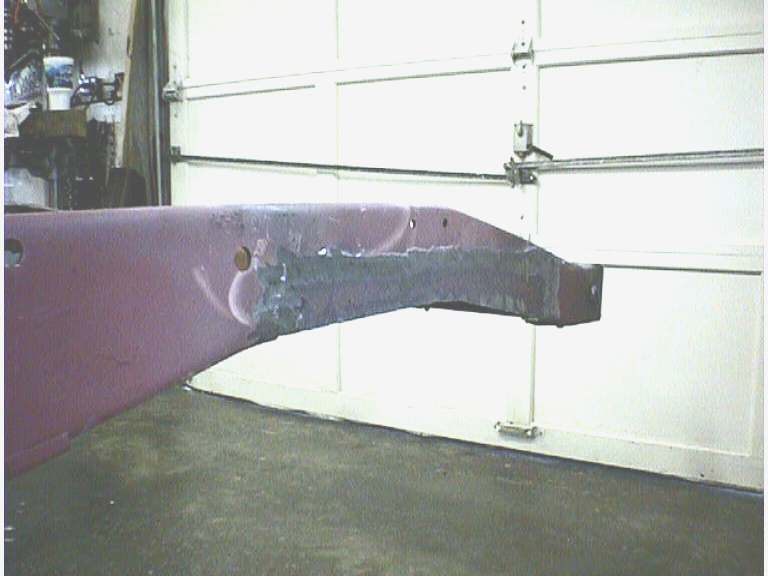
| Our original plan was to use 2x4 rectangular tubing... cut out two sides and we'd have a nice "L" shaped patch piece with a nice radiused edge. Well, we all know about plans. | |||||
|
|||||
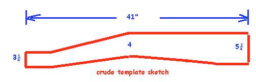
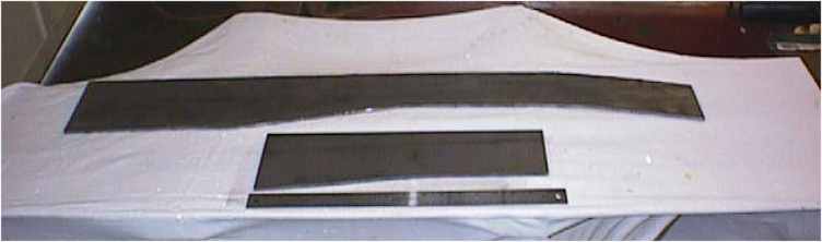
| The frame rail at this point, drops down 2-1/2" on the upper and lower edge and shrinks down from about 5-3/4" down to 3-1/4". all these curves and shrinks killed that idea. Seperate patch panels were patterned and cut. You just gotta love plasma cutters. The pictures below show the cardboard patterns and the patches in the rails. Another will be used to mend the lower portion of the rail. You can see them in the other pictures. | |||||
 |
 |
||||
 |
 |
 |
|||
The pictures below show the crude sketch for the frame boxing plates and the Heidt's plates compared to ours. The ruler in the pic is an 18" metal rule. Patterns were cut from cardboard and used to plasma cut the 3/16" steel plate that we used for the boxing plates. |
|||||
|
 |
||||
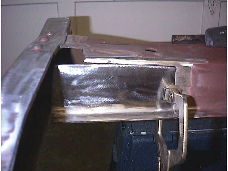
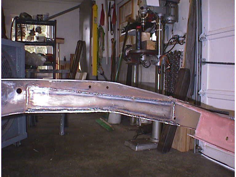
| The pictures below show the progress by the end of day two. The term 'Day one' and 'two' is somewhat misleading. Day one began at 5:30 p.m. and ended at 8:30 p.m. Day two began about 5:00 p.m. and ended by 7:30 p.m. so we have roughly 5-1/2 hours invested from the first plasma cut till now.. Both rails are complete, one of the boxing plates is finished and ready to weld in, the other needs dressing and fitting. The front cross member cuts are squared up and we need to bend the patch pieces. It won't be long now before the subframe is jacked into place... | |||||
 |
 |
 |
|||
 |
 |
 |
|||
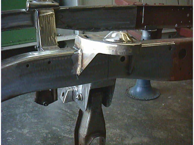
The next step is to weld in the boxing plates... then we will bend the patch pieces for the cross members, weld them in for a nice clean fit. I bent the patch panels for the crossmember from 11 gauge (.155) material on my press bender. I started with a piece about 8 inches long and 8 inches wide for the right side. I bent a 90 DEGREE angle about 1.5 inches from the edge, it's about as close as I can bend on my bender. I layed the new bent piece up against the trimmed holes in the cross member and marked the opening from the back with a felt tip marker. Then, fired up the plasma cutter and cut just outside the lines... this gave me a little trim material to allow for grinding into a good fit. I also marked the exact length of the flange at the bottom and cut it as close as possible.. grinding will make it look perfect. The same procedure was followed for the left side with it's dimensions a little smaller. The pics below show the patch pieces clamped in and ready to weld. (the little tab on top of the left patch was added after the welding on the left side... you'll see it in a later picture. |
|||||
|
 |
||||
| All the welding on the crossmembers and boxing plates
added up to about 17 feet of weld. It was done nearly continously... (not continuous
in a line...we skipped around to cut down on the heat on any area, but we never really
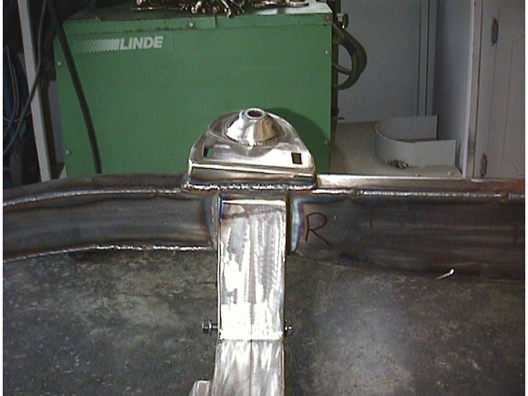
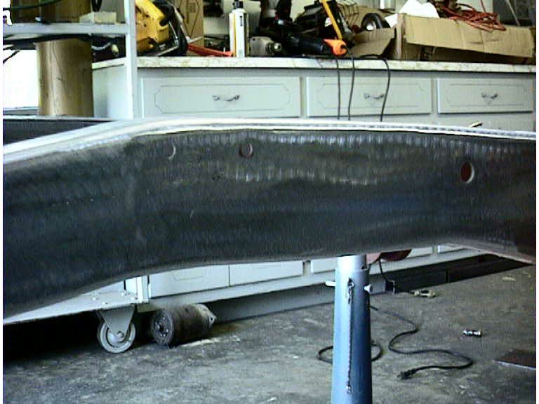
stopped welding except to change position. After the boxing plates and patches were complete we broke for lunch to let us and the frame cool down. After a sandwich and a 30 minute B. S. err... planning & stratagy session we returned and started our calculations for the crossmember placement. Heidt's gives their crossmember centerline location as 19-3/4" back from the center line of the front spring shackle hole... good dimension... easy to use... except the volare install had removed that hole when we notched the frame. Since the prime objective was to center the fender opening, we mounted up the fiberglass front flip and the rear section of the fender and found the center of the opening with a tape. We transferred that point to the frame rail with a carpenters square. We could cross check that point by using the front spring rear shackle hole (41" from the front hole minus 19-3/4" = 21-1/4" from the center of the rear shackle hole. AND the original wheelbase was 110" and we wanted the new axle center line around 1 - 11/2" ahead of this, so about 111" should work just right. The measurement from the rear shackle hole was 21-1/2" and the check measurement from the rear axle centerline was 111-1/2". Close enough for us ! We scribed this line on both frame rails and started marking the crossmember for it's centerline. We set the crossmember up on a floor jack and raised it into place. When all the centerlines lined up we tacked it on each corner and underneath. Two or three crosschecks on the measurements found us less than 1/32" off.. so the final welding began. The Heidt's crossmember was almost a perfect fit.. We found one 'oops'. Heidt's spaces their crossmember for the boxing plates to fit outside the frame rails.. we put ours in flush so they would dress out nicely. that gap had to filled with weld material and some of the gaps were the fault of the frame moving a little. I'm sure with the volare install, the volare removal and the patching... something had to have moved in or out a little. Dave made short work of the welding and after watching him work I'm still amazed at how nicely he does his work. My little Hobart welder had it's tongue hanging out when we finished for day. End of day three. Below are the pics of the progress so far... boxing plates in, frame patches complete and crossmember and tophats welded into their proper place. |
|||||
|
|||||
| The welds need to be dressed, but after that the only thing left to do as far as suspension, is bolt on the a-arms, spindles, rack, rotors. etc. New engine mounts and transmission mounts need to be fabricated and the rear crossmember will need to be adjusted. The original mounts with the Volare clip were all offset 2" to the right to allow for the steering box. We plan on centering up a little better now that we have room, so some adjusting will be needed. | |||||