Hopefully this article will describe with some clarity, how to install a new parking brake system in a modified 1953 Ford F-100 truck. When I bought this truck it had been sitting under a Sweet Gum Tree for about 7 years. The first thing I noticed when looking underneath, other than the wasp nest as large as a volleyball, were the cables for the parking brake hanging down on the ground. The cab end was rusted completely away and the brake handle was unmovable. Most old trucks will be in similar condition ... or worse.
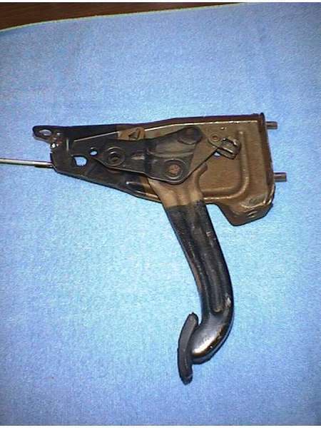
Now... here's how I connected the two ends together. The actuator (pedal) swap was relatively easy. I had been looking at the catalogs and saw all the shiny pull type levers and the pretty machined billet pedal assemblies. I couldn't seem to find a spot where I wanted to put the pull lever where it wouldn't be in the way and the pedals, while cute wouldn't show much once installed. A lot of money for a little show. Since it was mostly hidden from view, other than the little square pedal pad, I settled for a stock type pedal assembly. I found a foot pedal from a mid ‘80s Ford truck in good condition for $20.00 at the junk yard. With a little paint it will match up perfectly with my planned gray tweed interior scheme. It was almost a drop in unit. The original hand operated unit mounted to the firewall with two 5/16" bolts and to the underside of the dashboard with the same. The length on the new foot pedal was perfect and I only had to drill one hole in the firewall. I used one of the existing hand-brake mounting holes in the firewall and the same mounting hole in the dash as the original. The lower firewall and floorboards have already been replaced in my cab, so the old cable routing holes were gone. This was ok since I was routing the cables in a totally different direction. The old system used one control cable from the hand brake back to a bracket in the center of the frame, just behind the cab. An adjustable lever arrangement pulled a common bare cable that applied pressure to the brake shoes in both drum assemblies. It worked well for millions of trucks for years. With the modifications to the truck including new axle, ladder bars and coil over shocks, and a new exhaust system coming, there was no room for the old type system. After discussing options with other truck owners and reading all I could find, I decided that individual enclosed cables would need to be run to each wheel. Some folks who do this use junkyard cables and make brackets or adapters to fit it all together. The pictures and examples I've seen rival a factory installation. My problem here in Alabama is that when most yards take in a junker, as soon as the major pieces are removed, the frame is sitting on the ground. The dirt, oil, mud, runoff, not to mention forklift forks, do a real number on the remaining cables. It’s nearly impossible to find a good set of used cables and even harder to get the yard owners to remove them. Too much trouble for too little cash. So… I started researching after market cable makers.
There are several cable manufacturers out there. You only have to thumb through any street rod or truck magazine to find them. Examples are Inline Tube, Control Cable, Inc., Lokar, A-1 Brake Parts….. the list goes on. The options and prices vary from stainless steel braided beauties with teflon lined jackets to OEM type cables and the prices run the range from affordable to extravagant. If you’re building a show truck that will sit over mirrors with guard rails around it…. well, you know which ones to buy. I’m building a driver and just need dependable. I checked around and found that Control Cable, Inc (http:\\www.controlcables.com) could make cables to "my" specifications… any length, any type termination and charged a base price plus so much "per inch". They also can make throttle, clutch, hood and trunk cables. Even power trim cables for boats and parachute cables for dragsters. Since my truck's system was such a hybrid, this was my choice. Vic, their sales rep, faxed me a work sheet which described the basic setup and how to measure the cable lengths needed for my system. He suggested using vacuum hose, or something similar, to determine and measure the route for the e-brake cables. It’s very flexible and inexpensive. Probably 20 feet will be more than enough for any design project. I had some reasonably stiff 3/16" plastic tubing on hand. It supports its own weight and is flexible enough to work easily. That is what I used.
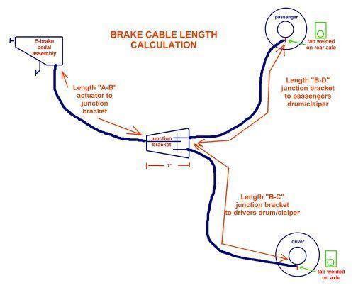
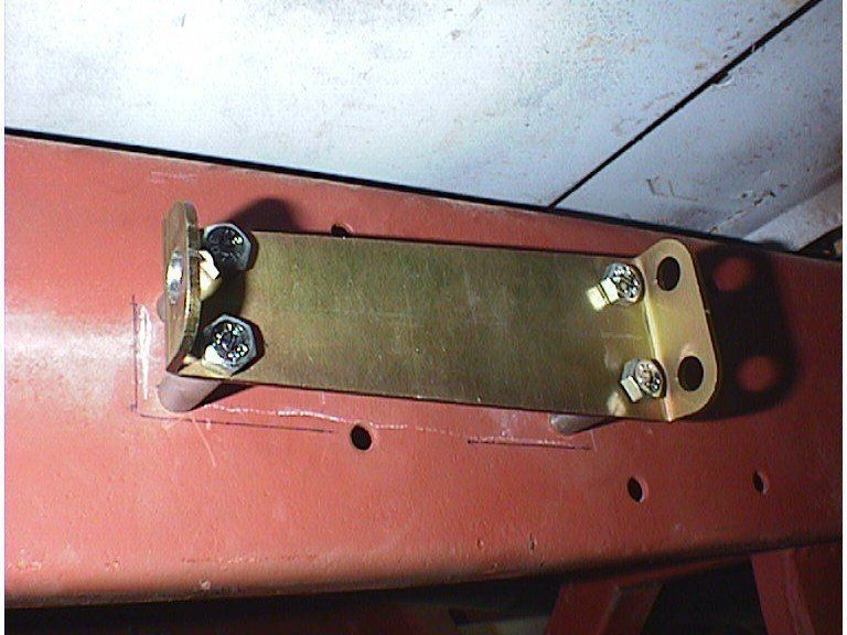
After I mounted the foot pedal and drilled the pilot hole in the floorboard, I snaked the tubing through the hole and along the left frame rail to a point under the cab. Whether you use individual cables or the common pull "Y" cable, there has to be a central point where the cables from the rear wheels meet with the cable from the actuator in the cab. I choose the outside of the left frame rail. Control Cable sells a "Junction Bracket" that mounts to the frame with attachment points for the three cables, this is also the adjustment point for the system. I marked the location for the bracket on the frame rails. This bracket would be easy to fabricate. It’s seven inches long and wedge shaped. But, for a few dollars the time saved was worth more to me. With these points marked on the frame it’s a simple matter to roll out your tubing from point A (foot pedal) to point B (junction bracket) and measure it. Repeat this procedure from point B to point C (left drum or caliper) and from point B to point D (right drum or caliper). Note here… the dimension you need is not end to end… it's from mounting point to mounting point . My cable housing ends in a tab under the rear axle, but the cable continues on to the caliper… call your vendor if you have any questions.
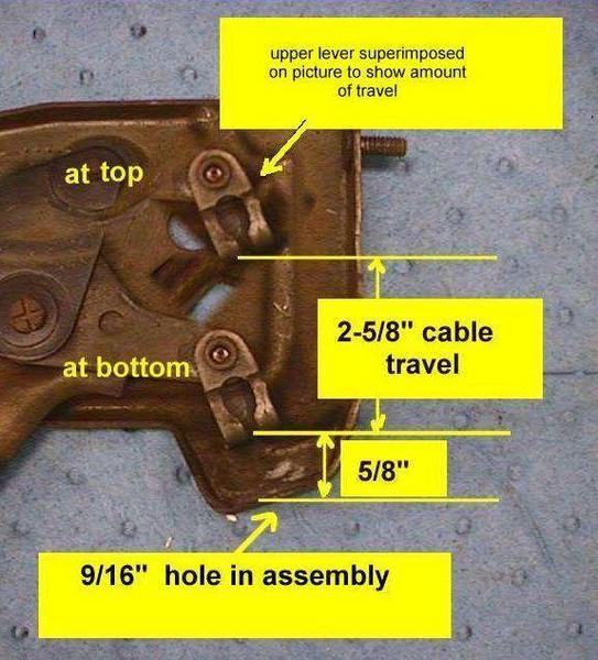
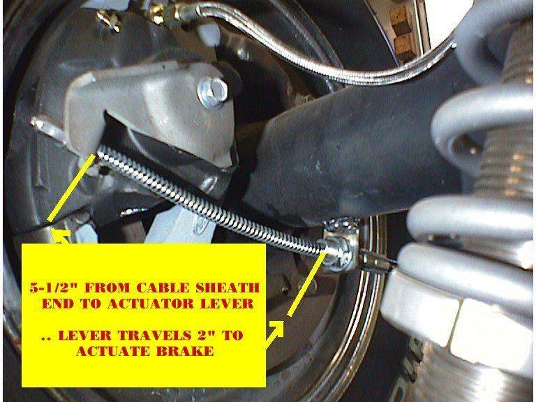
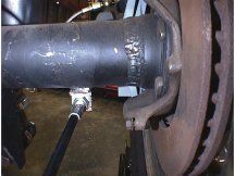
Make yourself a sketch like the one above and write down the dimensions. Then transfer them to the worksheet. This is the cable sheath length. You will also have to tell them what kind of terminations you need on the ends of the cables. Mine needed a swaged-on ball at the foot pedal and at the caliper ends also. You will also have to determine the length from the mount point of the cable sheath to the actuators ( from the end of the cable sheath to the cable clamp on the pedal and from the other end of the sheath to the brake drum/disc actuator). And finally, the amount of travel the cable needs to apply the brakes. This gives you the movement length for the cable. Looking at the picture below, you can see that my cable housing end will be in a tab welded on the axle housing and there is 5-1/2" of cable length from the tab to the actuator. In addition there must be 2" of travel in the cable to actuate the e-brake mechanism. The same dimension are needed on the pedal (or handle) end… the length of cable out of the housing and amount of travel.
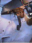
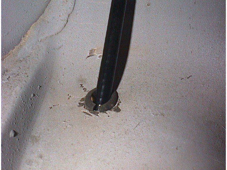
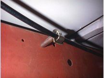
With all this information, they can build a set of custom cables to fit your application perfectly. Although more expensive, (each of my 3 cables was around $35.00) it's a much easier installation than trying to make junkyard cables fit and fabricate the couplings, brackets and do-hickeys needed. The older I get and the longer my truck project takes, the more important "easier" gets to me. After your pedal assembly is mounted in the cab and you have an adequate access hole through the floorboard, the first thing you should do is insert some type of grommet or "wear protection" in the hole. It won't take long for the rough metal edge to chafe the cable assembly. My picture here shows a temporary rubber grommet that is normally used in electronic applications. It will be replaced with a boot assembly that offers a little better protection and seals the hole better.
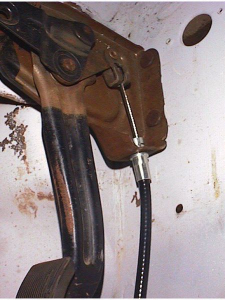
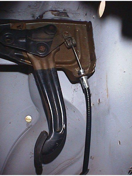
Put your actuator cable up through the floor board and into the mounting hole in the pedal assembly. Drop the swaged ball into the hanger and slide the "C" clip into its groove… this end is done. Except for adjustment when the system is complete.
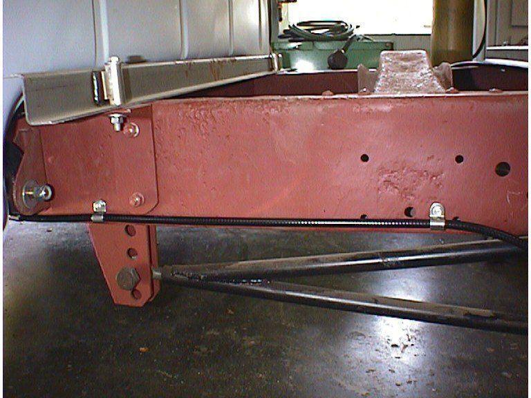
My Junction bracket was mounted on the outside of the frame rail. So, I routed my actuator cable down between the cab and the cab mount to the junction bracket. There was one obstacle in this mount that I had overlooked. I had taken the running board mounts off and had forgotten about them… so I had to fabricate a mount that would raise the junction bracket up enough for the cables to clear the running board mounts. The next pictures will show these mounts. They are simply 1-3/4" sections of 3/8" tubing. Another thing I missed originally was using 5/16" bolts to mount the junction bracket. The heads of the bolts didn't allow the nuts on the rear cables to make up. So I used 5/16" for the front two holes and 1/4" for the rear two. It was probably a bit of over kill, but I try to use the largest hardware that will fit. I also fabricated a clamp for the cable between the cab and the bracket. I could have clamped the cable directly to the frame, but it would have put a pretty good bend in the cable so I raised the clamp to match the junction bracket height.
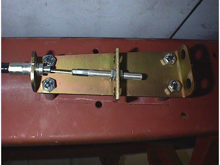
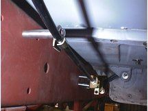
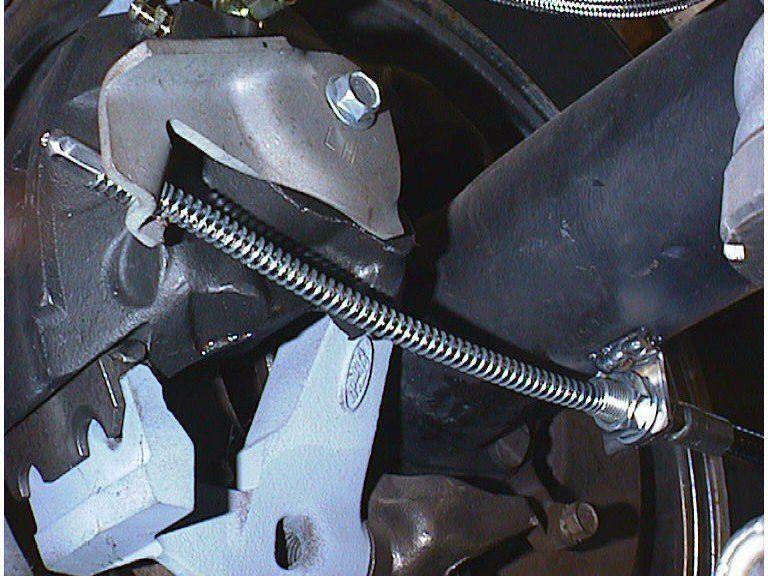
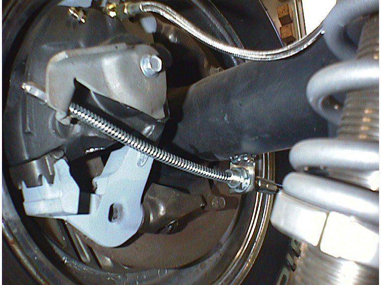
So… now you have the front half of the system installed…. easy wasn't it ?? We'll move on the rear portion now. Secure the two rear cables into the bracket and attached the swaged ends to the pull bar. This is accomplished with two neat little inserts that hold the cable in place. Stick the cable end through the pull bar… slide the insert over the cable and up to the ball…then move the whole assembly back to the pull bar and it is secure. The inserts have a tight friction fit into the pull bar. At the axle end of the installation I welded a tab with a 5/8" hole to the underside of the rear axle. This would be the rear mounting point for the brake cable. For the left side the route was simple…under the rear cab mount and straight down the frame rail and turned out from the frame to the tab. The cable was clamped directly to the frame rail using stainless steel clamps and self tapping sheet metal screws.
The right side was a little more complicated in it's path. The cable left the junction bracket and over the rear cab mount and left frame rail. Then, under the front bed support rail and the middle cross member. Under the right frame rail, and down to the tab on the axle. The clamps hold it tight at the middle cross member and under the right frame rail. This isn't a complicated installation. The pedal operates smoothly with no bind and no friction. The final adjustment will be done after the rear pads are installed and the brakes completed. The planning and measuring take nearly as long as the actual installation, but they are the most important part.The old carpenters axiom "measure twice cut once" could be adapted here to "measure twice, order once"... I didn't ask Vic, but I'm sure that Control Cable would rework a cable that is too long, but they would have a hard time lengthening one. Measure carefully. Boilerplate denial of liability statement… i.e. the fine print This device is something I came up with to prevent me from spending too many dollars on a commercial patented device, although that part of the plan didn't work. It is not patented, engineered or even perfect… it is what it is, a homemade contraption. I’m sure there are alternatives to this design some even better/cheaper/easier, I just didn’t think of them or warrant them necessary... there are several similar units on the internet waiting behind Google for you to see/copy/build…(just like I did) This work was done by me and for me or by friends who were nice enough to help me out. I only ask that if you reproduce it give me credit for it and if you make money from it… give me my percentage. Since I have no way of knowing your level of competence, welding or cutting skills, mechanical ability or estimated intelligence, there are no guaranties or warranties either verbal, written or implied with this article. Along with this article I am giving you absolutely free of charge…that’s right ! FREE !!...the liability, total and complete liability for the use or misuse of this contraption will be yours and yours alone. It belongs to you and keep that in mind… I am in no way responsible for any damage, injury or embarrassment you may suffer from the use of this homemade device. If it doesn’t look like something you’d be comfortable using… don’t build/use it. If you’re not intelligent enough to make that decision about your comfort level… ask a family member or friend.. but here’s a hint… if you have to ask someone… don’t build it ! Pictures were made at different stages of construction and all assemblies in pictures may not be complete in each shot. I.e.. a picture showing ‘some parts’ only means that it was not finished, but I’ve tried to make the idea complete to the best of my ability. If you have questions or see mistakes or problems, let me know by e-mail and I’ll make the corrections if possible.. Use these ideas at your own risk. Modify them at your discretion and to suit your purpose. Your mileage may vary, batteries not included, much assembly required... wait one hour after building to enter the water, additional charges may apply. not all applicants will qualify for advertised A.P.R., for ages 10 to adult…side effects are comparable to placebos. Do not take drugs when building or operating machinery. JUST SAY NO. Copyright . 2012 John Niolon, All International Rights Reserved. This document may not be copied or published without prior written consent of the author- jniolon@att.net
|