Installing a Mechanical Brake Light |
(after 3 Hydraulic Switches leaked) |
by John Niolon |
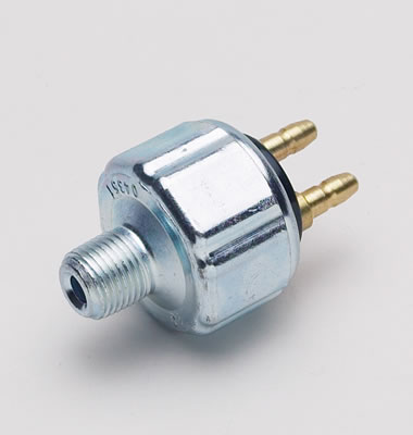
Twenty years ago when I started on this truck one of the first things I did after an initial cleaning and blasting was to install fuel and brake lines. The brake lines included a hydraulic brake line switch. You know.... the kind that actuates the brake lights when the brake line pressure activates the switch. Simple enough, eh ? |
|
| Well, fast forward 20 years and I'm filling the system and bleeding the brakes. Of course, I found a couple of fittings leaking (you can't make a perfect flare everytime, can you ?) So I got those fixed. A day or so later is see a spot on the floor under the truck, so I creepered underneath and found the problem. The brand new (albeit 20 years old) hydraulic switch was dripping brake fluid onto the floor. Fair enough, it is 20 years old, a quick trip to the auto parts store and in 30 minutes a new switch was installed and that line was bled again. |
| Want to guess what I found the next day ??? Another switch leaking. This time I didn't use the a/p store chinese universal replacement for 5.99 I replaced it with a high $$ unit sold by one of those online racing places... a name brand unit for 15.99 plus shipping (money being no object when building your truck) . I installed it, bled again. Guess what ?? well, you get the picture. |
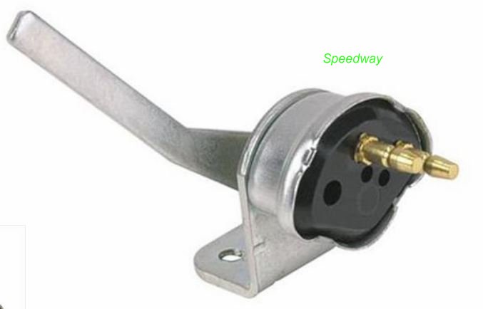
| Plan B - change plans. Researched and you-tube'd the options and found out about mechanical switches...so I decided to go mecho/e-lectrically. Bought two switches., one from Speedway and a Keep-it-Clean version... My thinking was
one might be different than the other in operation... found out that both work
identically... and opposite of what I thought they should. They are spring loaded and in
the 'resting' position the switch is open... the brake lights are off.. As you move the
lever on the switch the internals make contact and the lights come on. To me that meant
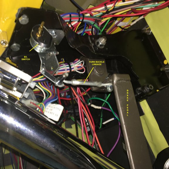
the switch had to be in front of the brake pedal so the pedal action could pull the lever.
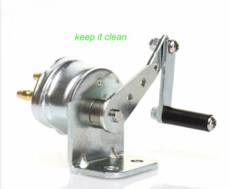
The Keep it clean model seemed to have better adjustment options so I used it and I
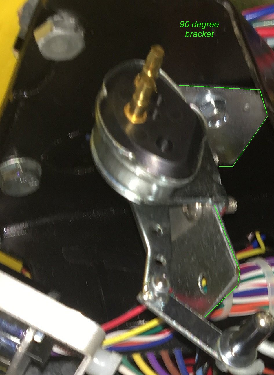
mounted the switch to a 90 degree bracket and then screwed that bracket to the brake pedal
framework under the dash. That was the easiest part.
Now to 'unplumb' the
hydraulic leaker, bend another tube to add an inch to the line and bleed again... oh, and
reroute the switch wiring from under the cab to under the dash... |
| Boilerplate denial of
liability statement… i.e. the fine print The installation of this device is something I came up with to prevent me from spending too many dollars on a commercial install, it is not patented, engineered or even perfect… it is what it is, a home made installation. I’m sure there are alternatives to this way of doing things... some even better/cheaper/easier, I just didn’t think of them or warrant them necessary... there are several similar units on the internet waiting behind Google for you to see/copy/build…(just like I did) This work was done by me and for me or by friends who were nice enough to help me out. I only ask that if you reproduce it give me credit for it and if you make money from it… give me my percentage. Since I have no way of knowing your level of competence, welding or cutting skills, mechanical ability or estimated intelligence, there are no guaranties or warranties either verbal, written or implied with this article. Along with this article I am giving you absolutely free of charge…that’s right ! FREE !!...the liability, total and complete liability for the use or misuse of these installation ideas will be yours and yours alone.
|