|
WIRING A '53 FORD F-100 OR NOTES
ON INSTALLING AN EZ-WIRING KIT IN A '53 F-100 |
|
|||
| This isn't going to be a step by step wiring tutorial. It's just a collection of ideas and things that I did on my truck. I'd never wired a truck from scratch before and while there are several youtube videos on the net on the subject, they didn't really cover the areas where I was looking for details. Editorial note... I put this article out for critique on some sites and got some excellent suggestions, additions and critique. I'll add these in where I think they should be in red text. Things like routing and where to put 12 volt termination points, what circuits needed relays and where extra fuses and such were needed. I used a E-Z Wiring 21 circuit harness kit. It uses color coded wiring with the circuit use stamped every 5-6 inches along the wire. That was very helpful but sometimes dim black writing on dark purple wire was a challenge... lots of light and magnification helped with that. While I did like the kit I was somewhat disappointed with the 14 page instruction manual. Lots of detail missing, or at least I thought so. The tech guy on the phone is very helpful but it's tiresome calling him with every question. There is also no circuit diagram. I like to see what goes where and what path it took.. They don't offer that. Some of the others do. One in particular had an instruction book..., 47 pages... lots more detail for the rookie like me. This is a total wiring job, not a rewire or 12 volt conversion. So I don't have the advantage of seeing where things went and deciding to follow that path or not... but usually the battery location and voltage regulator and solenoid are in position. I got a blank slate. Now... some of your old hands or gurus might read this and say 'what a dumb***... why didn't he do this... or that' and that's cool. I admit up front that I've never done this, seen it done, helped do it or even given much thought to it until now. So, old timers... just enjoy your laughs.
|
|||||
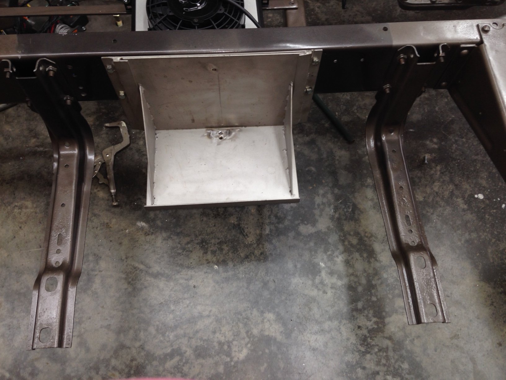
| Before the wiring begins you need to have some locations in mind... like where the battery would be and the starter solenoid. Let's begin with the battery location. I chose my battery location as under the passenger side, outside frame rail in a drop down box I built to copy the commercially available ones. Pretty much centered between the running board brackets. The starter solenoid is mounted just ahead of the box. I used 00 ( that's called two ought cable) gauge welding cable for battery cables with ends soldered and crimped. They worked out to be more expensive than regular auto parts store cables but will give me better voltage/current supply and less problems in the future. A freshly built 460 is pretty tight and has a high amp draw to turn it over.. heavy cables will supply the amps the starter will ask for. | |||||
  |
|||||
|
|||||
| EDITED
more detail on battery cables. I've gone back and added more detail on the battery cables. I really
kinda skimmed over them above. The cables that connect the battery to the power
suckers and to the truck frame for ground are probably the most important set of wires
you'll have to deal with, so a little more attention is warranted.
Everything... EVERYTHING that uses power in the truck gets it initially from these
cables. So, the better they are, the better everything else will operate.
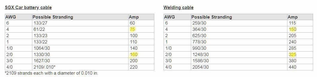
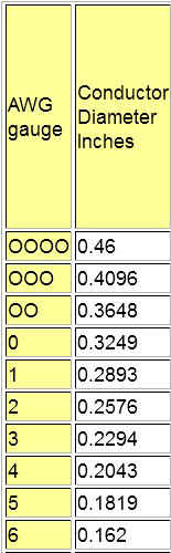
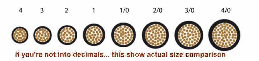
Wire type and size You can buy standard auto part store or heaven forbid Walmart battery cables with undersized wire, questionable connectors and Lord knows what for insulation. If you do.... you can stop reading now. They might work for your Civic 4 cylinder but will be woefully undersized for your ride. I've seen them in #6,#4,#2 and even 1/0 (one ought). The lower the number the larger the conductor. Personally I wouldn't use less than #4 for anything and it's what I used for runs to my 12vdc distribution points. I'll show you a couple of charts for comparison. First is a chart showing cross sectional view of wire by gauges... looking at #4 vs 2/0 you can see an obvious difference. More wire, more current, less resistance and heat.
|
|||||
  |
|||||
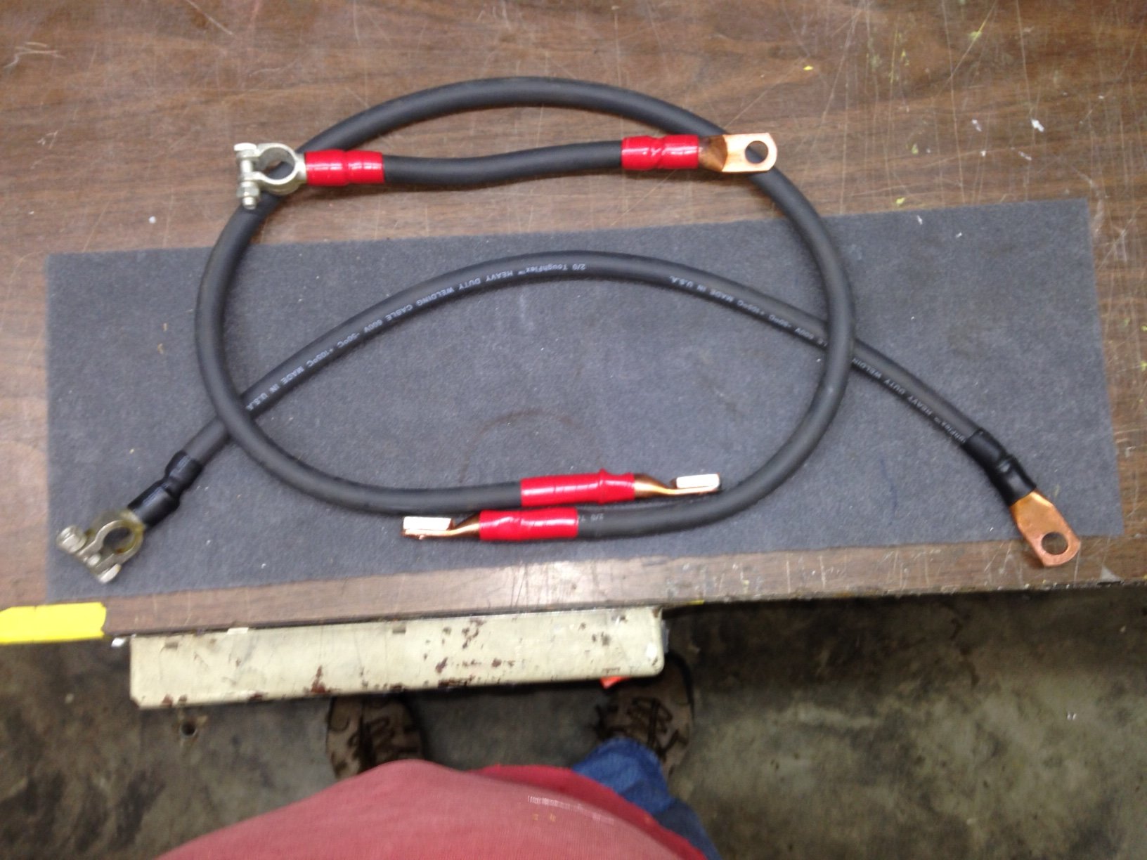
| Battery cable vs welding cable. The only advantage I see that battery cable has over welding cable is the insulation is more resistant to automotive chemicals/oil/etc. Welding cable is more flexible, due to a higher number of strands of a smaller size and has a higher current capacity. Almost or exactly double. The chart below shows the differences. I'll also mention that welding cable is more expensive if that is a consideration.
|
|||||
|
|||||
| Connectors
There are a gazillion different types and grades of battery cable
connectors. I opted for crimp on for the copper lug ends that connect to the frame
and solenoid points. (but I still soldered) and solder type for the battery terminals. The
ones for the battery have a 'slug' of solder and rosin inside the connector so they are
ready... just insert cable and heat it. These will need more heat than your 50 watt
iron... a small propane torch used sparingly does this much better. After it
cools, slide the heat shrink tubing up and over the connector and apply
heat. I used good quality adhesive lined heat shrink tube to cover my
connectors . When heat is applied, the adhesive lining melts and flows,
encapsulating and sealing components contained within the shrink tube and bonding
permanently to a cable or connector. Then I marked them for polarity using 3m
scotch electrical tape. It would be hard to mix them up, but I'm a belt and
suspender kinda guy. Rather than try to explain all the different connectors and their pros and cons ... use the link below to find out ever so much more than you wanted to know about connectors. It as a world of good info on all types of connectors and are very easy to deal with. I will tell you that there is a difference in positive and negative connectors as the post are different sizes. But, the ever available 'universal' is always there for you lazies. It's up to you, your application and mounting point will probably be different from mine so your choice.. oh..and your Visa limit might enter into the equation. But knowing what we have invested in these trucks.. a few bucks more isn't gonna make that much difference. |
|||||
https://www.powerandsignal.com/Images/PDFs/Catalog_Full_Line__English_Connectors.pdf
|
|||||
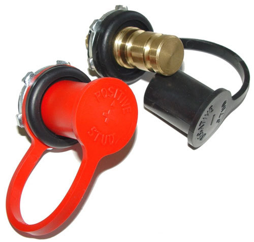
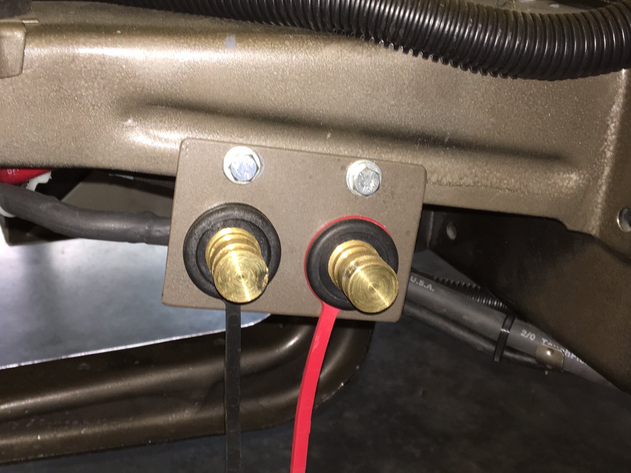
| My truck
has a fiberglass tilt front end and shaved door handles and the battery is sitting in a
drop down box that's attached to the frame behind the passenger running board. It's
a little (well, a lot) awkward to access with jumper cables if your battery dies.
The battery and box weigh around 50-60 pounds and it's a chore to lower it and raise it
when you're lying under the running board. To solve this jump start dilemma I
purchased a set of remote jumper terminals. I didn't buy the ones with the fancy mounting
bracket since I didnt know where I would put them... I just fabbed up a bracket and
attached it to the cab mount right behind the passenger side tire (easy to access)
It's connected to the battery with #4 wire.
|
|||||
|
|
||||
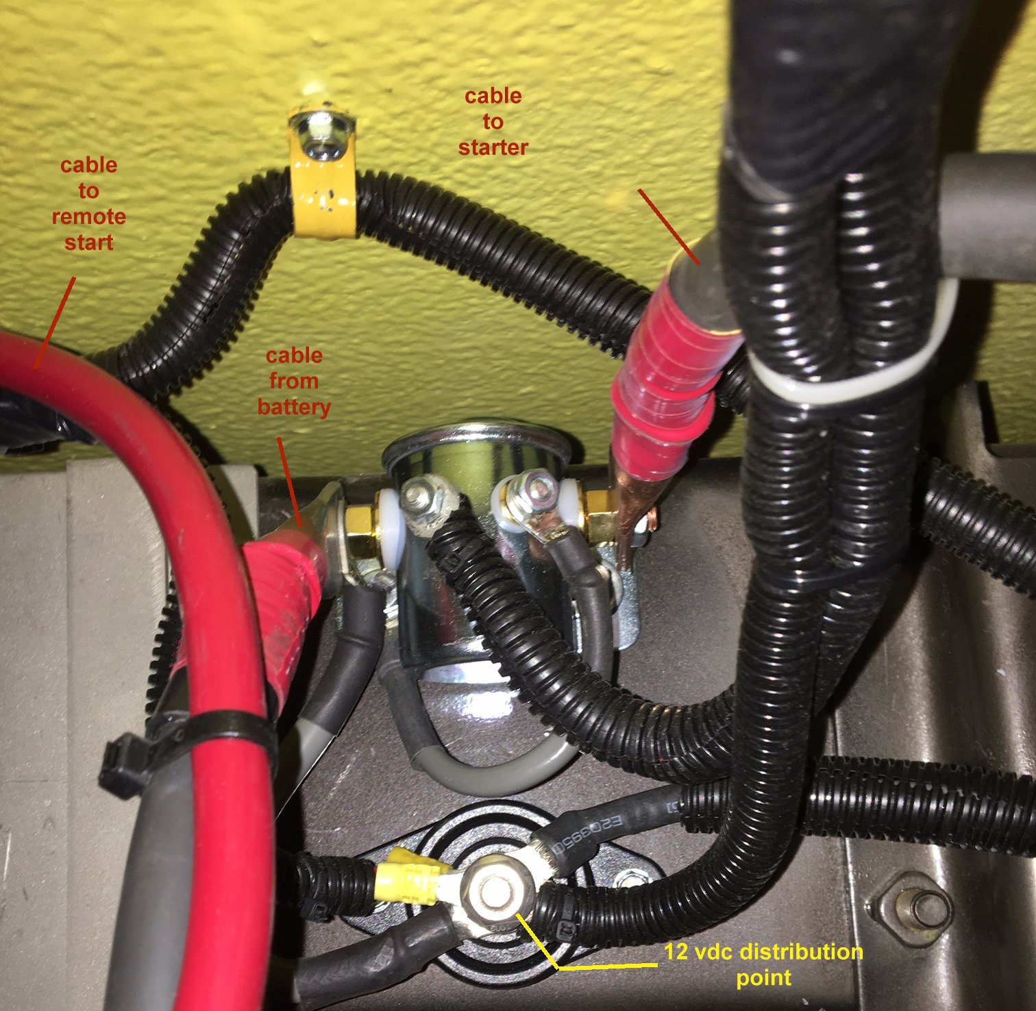
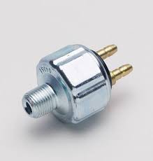
One last comment on the battery and connections. The starter solenoid. When I first fired off the truck all was ok. When I tried it after the wiring was done the starter solenoid stuck keeping the starter turning. I didn't include a manual cutoff switch so it was run around the truck to the starter side and figure out what to do. The battery was tucked up in it's box so removing the cables was out. I finally tried taping on the solenoid several times till it released. It was brand new but I didn't trust it... bought another auto parts store solenoid.. installed it and the same thing happened !!! I later discovered that a/p stores usually stock imported low amp solenoids (50 amp contacts) that will stick. So.... To the internet !!! A little googling and I found a Cole-Hersee continious duty 200 amp solenoid that would handle the amps. No more problems..., I only mention it as it is a common problem I discovered after doing the googling. |
|||||
| Now,
back to the wiring stuff. With the battery location and cable decision made I opened the box and drug out the wiring harness. There is a mess of stuff in that box.
|
|||||
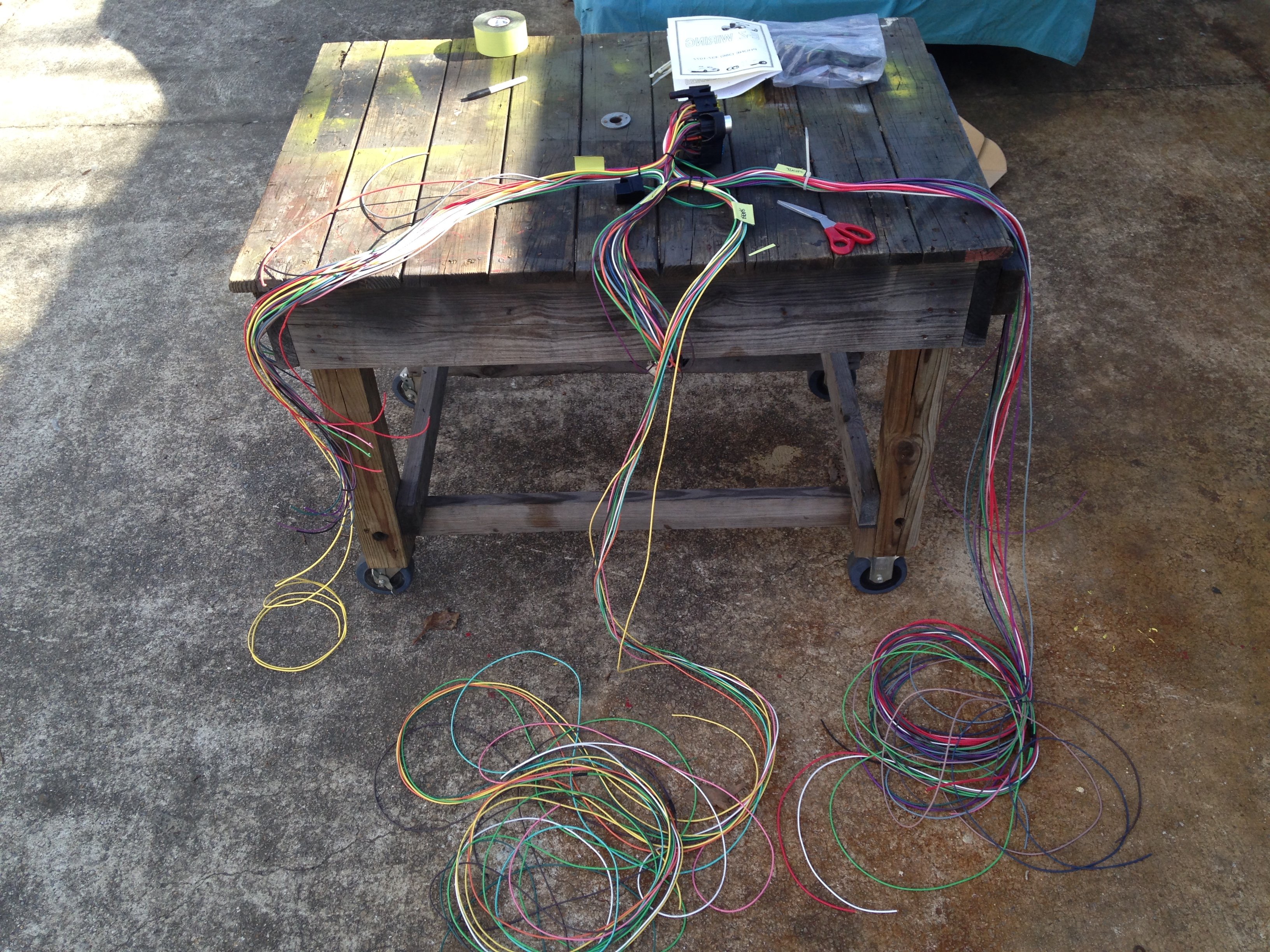
| I
started by getting out in the sunshine on a work surface. The manual suggested using
the shop floor. I'm 70 y.o. and working on the floor isn't as fun as it was when I
was a kid with toy cars. I began separating all the wires into groups and using the
instructions for reference I made sure the wires I needed were in the group they should
be... there's a lot of wire to sort out, but basically there were 4 groups...
FRONT assembly (lights, turn signals, engine cooling fan, a/c compressor, distributor, tach, oil pressure unit and water temp sensor, solenoid wiring and horn, etc.) everything forward of the firewall goes in this group. One wire I removed from this group was the Power Antenna. Mine is in the back corner of the cab so it's actually in the back group. Another was the alternator exciter wire.. I'm using a one wire alternator and don't need that one. Look at each wire and mentally picture where the wire will terminate. This is a generic kit so your plan might not be in their initial plan.
INSTRUMENT PANEL group... that's pretty clear there but check it anyway. Just think about what is in your dashboard and include/remove wires accordingly. The column wiring group is in this area and will take some deciphering depending on what column you have and if it has ford or chevy or chrysler wiring.
CAB group. This included radio (pulled from the instrument panel group) mine is in a console, a/c or heat, doors, windows (if they are electric) cab and dome lighting and 3rd brake light (which was pulled from the rear section..it's actually IN the cab. While your power wire for the windows and doors might go directly to the doors, lines for the switches operating them have to be considered also. Mine will be in a console, yours might be in the dashboard or in a dash extension panel under the dash.
REAR END group. This includes brake, tail, tag, backup lights, fuel pump, fuel sending unit...basically everything behind the cab. You might also consider transmission cooler (I used fuel pump line for that) and trailer wiring, if any and that can be spliced in to the rear lighting circuits now or later.
|
|||||
|
|||||
| Spread
each group out separately and maybe secure it with a wire tie around them in a
couple of places just to keep things neat... and a label wouldn't hurt. There is another group of wires that the book never mentions... well, actually two. One is the grounds... You need ample ground wires to connect grounds from battery to frame (well, duh?) but also from the frame to the block of the engine. I used 00 welding lead for the main ground from the block to the frame and #4 wire with crimped on connectors and shrink wrap at the ends for the secondary ones... bolted to clean metal to make good electrical connection... paint does not conduct electricity worth a damn... any connections you make to the frame, fenders, cab etc need to have the paint scraped off both sides and it wouldn't hurt to add a little dielectric grease to the metal to help with conductivity and forestall corrosion and rust. I ran grounds from frame to cab, frame to transmission, frame to bed, and since I'm running a fiberglass front flip I grounded from frame to hinges and hinges to grill for a good light ground up front. I've been a ham operator for years and we found when running mobile radios that grounds were essential to good transmission quality and receive capability. In a Volkswagen beetle I even had to ground the short tailpipes to do away with noise in the receiver, you can't have too many ground circuits.
|
|||||
| The
other group of wires not mentioned in the book is comprised of all the wiring for switches
and relays and such. For instance... there is a power wire for power windows in the
harness, but that doesn't do anything but supply voltage to the motor. You need a
relay in the circuit to handle the current of the motor.. then you also need wiring to
activate the relay from a switch mounted somewhere.. might be in the door... might be in
the dash or a console.. You might as well get an order together from ebay or amazon
for several rolls (multi-colored) of #12, #14, #16 and #18... a few feet of #10 wouldn't
hurt either. You want to order fine stranded "Primary" wire as used in auto and boat wiring... Good grade wiring is more expensive. You'll see a lot of 'deals' offering lower prices on CCA wire... don't bite. You want stranded bare copper, jacketed polyvinylchloride (PVC). Nomenclature GPT. There is also GXL which has a higher temperature tolerance and great for engine room applications. They both offer excellent resistance to oil, grime and flame. Reputable suppliers are Wiringdepot.com, Waytechwire.com, Delcity.com. After a few minutes on the net you can spot what you need by the price per foot or reel.
|
|||||
| The CCA wire is not pure copper... it's actually copper clad aluminum. It has a higher electrical resistance than GPT (read lower amps delivered over same length of GPT) and can become brittle and break. For a few dollars more buy the good stuff... How much do you have invested in this ride ????? Do want to scrimp on the electrical system that makes it run ????? | |||||
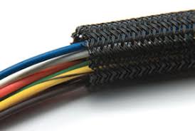
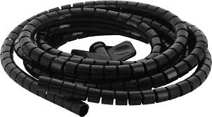
| Another thing you might want to consider is some type of covering or loom material for your bundles or even single wires. It will protect them and also dress up the engine room, under dash or rear end of your truck... nothing looks more amateur than seeing a vehicle traveling in front of you with wires hanging loose under the rear end, or the engine compartment with a rat's nest of wiring all over the place. Plus it's a nightmare to trouble shoot. It comes in all colors, even chrome and all sizes... one suggestion... when you're sizing what you need, buy the next largest size.. you can thank me later... most auto parts stores have a limited selection and even the big box stores... It's also all over behind Google or Amazon... here's some examples | |||||
|
|||||
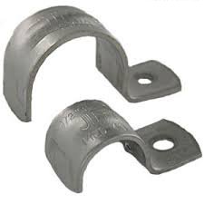
| You'll also need some clamps/clips/hickey things to hold it to the frame or firewall or cab floor or where ever you're installing... I used standard electrical conduit clamps... there are others available in billet, stainless, plastic, but decided I didn't need the bling as most of mine will be hidden . I did bling mine up a little... I painted them to match either frame or body color to blend a little better. I used standard self tapping sheet metal screws to attach them. I emphasized self tapping unless you want to drill each pilot hole for each screw....even I'm not that crazy. Throughout the article you'll see me attach things to the cab floor with the self-tappers. I used the shortest screws I could find and after attaching several places the screws poked thru the soundproofing and insulation. I carefully cut sections of the mats out... ground the screws down almost flush and reapplied the soundproofing and insulation mats and added an additional layer of tape to cover them.. | |||||
|
|||||
| I
did all the wiring BEFORE the exhaust system was built/installed. About 1/2 way through
the process a light bulb came on and I started thinking about the exhaust heat affecting
the wiring/loom. The pipes will be within a couple of inches of a few loom runs and
I'm sure things will get warm there. I researched hi-temp exhaust wrap and decided
against it due to comments and columns I read mentioning header ruin, water retention,
etc. Now I'm researching heat shields.. both metal and foil/fiberglass wraps...
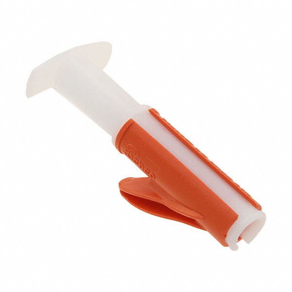
Now, that's nearly all the preliminary stuff... except for this..., If you opt for the plastic loom (convaluted) spring a few bucks for the install tool. You'll need two or three sizes, but the save you heaps of time and finger covering. Look here... https://www.delcity.net/store/Loom-Insertion-Tool/p_793214.h_793215 and the instructional video http://www.youtube.com/watch?v=wtycPTqURtk
|
|||||
|
Before we do the deed I need to mention a couple of things about terminations. Most everywhere you read it says to crimp the connectors on the wire... giving very little detail on types of connectors or tools to use. Let's look at termination types.
|
|||||
| CRIMPING... Crimp on connectors come in several different shapes.. each shape has it's own use. There are ring, spade, quick disconnect, butt splices and more. You will be using mostly standard ring connectors . connectors are sized according to the wire size being used. Be sure you're using the proper sized connector to get a good crimp. Most of the wiring in these kits is #16 thru #12 with the majority being # 14. So your ring connectors should be the 'blue' 16-14 size connectors. Every hardware, grocery, auto parts and even quick mart tool tables sell crimpers. From a buck up. Most are fair, some are junk and some will even hurt you. Invest in a good set of 'ratchet' crimpers.. they have a die set that properly fits the ring connector barrel and will crimp it evenly and with the right amount of force. The drug store variety just have an indent in the jaws to make the crimp... this is not good enough for you ! You can spend anywhere from 15 bucks to 200 bucks on good crimpers... the High $$$ ones are for commercial and professional folks who depend on their tools to make a living... they have multiple sets of dies and configurations. You need a set that will do crimps on #18 thru #10 wire mostly, so don't spend all your lunch money on the others. | |||||
| So buy
your crimpers, gather your assortment of connectors... and here again, don't get them at
the dollar store or import mart. But good connectors from a reputable electronics
store or the big box stores electrical dept or auto parts store... they are worth the
money. They come both insulated and non--insulated. Use the insulated for
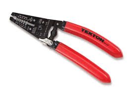
crimping. I use the non-insulated for soldering. Next you need some
strippers. Don't mortgage the farm... the big box stores and tool places sell good
strippers for a reasonable price... cheap stripers will nick the tiny wires and even
remove some of the strands with the insulation. Cheap tools don't save you
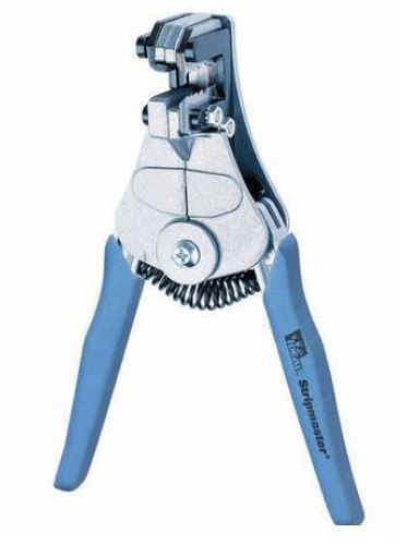
money in the long run. Using your new strippers, remove about 1/4-3/8" of insulation from the wire or roughly the length of the barrel of the connector. If it frays out a little give it a little twist to mold the strands together. slide the bare wire into the connector barrel. Now, most ratchet crimpers won't release until the crimp is completed (the handles come together and click) that insures a tight, secure crimp. Wrap your crimpers around the connector...make sure you have the connector, in the proper set of dies (usually color coded) then squeeze it until it unlocks by itself. Keep a watch on your wire making sure it doesn't slide back out of the connector. Here's some samples of the various tools. look at the big box stores or behind Google for best buy in these. BTW I love the Blue Ideal ones below, they hold the wire and strip it in one squeeze. |
|||||
|
|||||
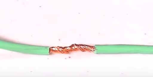
| SOLDERING Probably 90 % of my wire to wire connections are soldered. They are stripped ( about 1 inch off each wire) .... BEFORE you twist them together slide a piece of heat shrink tubing of the proper size and slide it up the wire away from the heat of the soldering iron ( most heat shrink won't shrink more than 1/2 of it's diameter so don't put a 1/2" diameter piece on a # 14 wire) then twist the stripped ends together tightly to make a good mechanical connection... I usually make an "X" with the wires crossing them halfway up the stripped part and then twist one clockwise and the other counterclockwise, wrapping each twist around the straight part of the other wire (easier to see than explain so look at the picture below you CAN pull them apart if you try but they are smooth and tight. | |||||
|
|||||
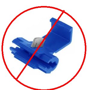
| Note... I haven't mentioned one other option... Skotch-Locs. These are those auto parts store add a circuit things. A plastic shell with a piercing piece of wire that pierces the insulation and wire when pressed , then the little plastic cap is put in place. All you need to know about them is DO NOT USE THEM !!! They aren't waterproof, they usually don't make good connections without damaging your wire, they look like crap and invite rust/corrosion and death to circuits. They keep the trailer renters in business, but they don't put them on THEIR car now do they ??? If you see them, turn and walk away. | |||||
|
|||||
| Soldering
iron.. NOT SOLDERING GUN !!!! You need a soldering iron in
the 20-50 watt range... not the megga guns that Weller sells that can go to 250 watts...
way too much heat. There are several good videos on youtube on how to solder.
Watch the ones on soldering WIRE not plumbing... you can even find one that will make a
NASA soldering expert out of you. Watch the techniques and practice them.. learn how
to clean your soldering tip and 'tin' it. Basically you need a low wattage iron,
flux core solder (not solid solder or plumbing solder that needs separate flux) and maybe
a small soldering clamp to hold things together. You apply heat to the wire with the
iron and after a few seconds apply the solder TO THE WIRE NOT THE IRON The solder
should melt and flow into the strands of the wires. When all looks encapsulated with
solder, remove the heat. Do not move the wires till the solder has solidified...
moving them as they cool causes a bad connection called a cold solder joint. You don't
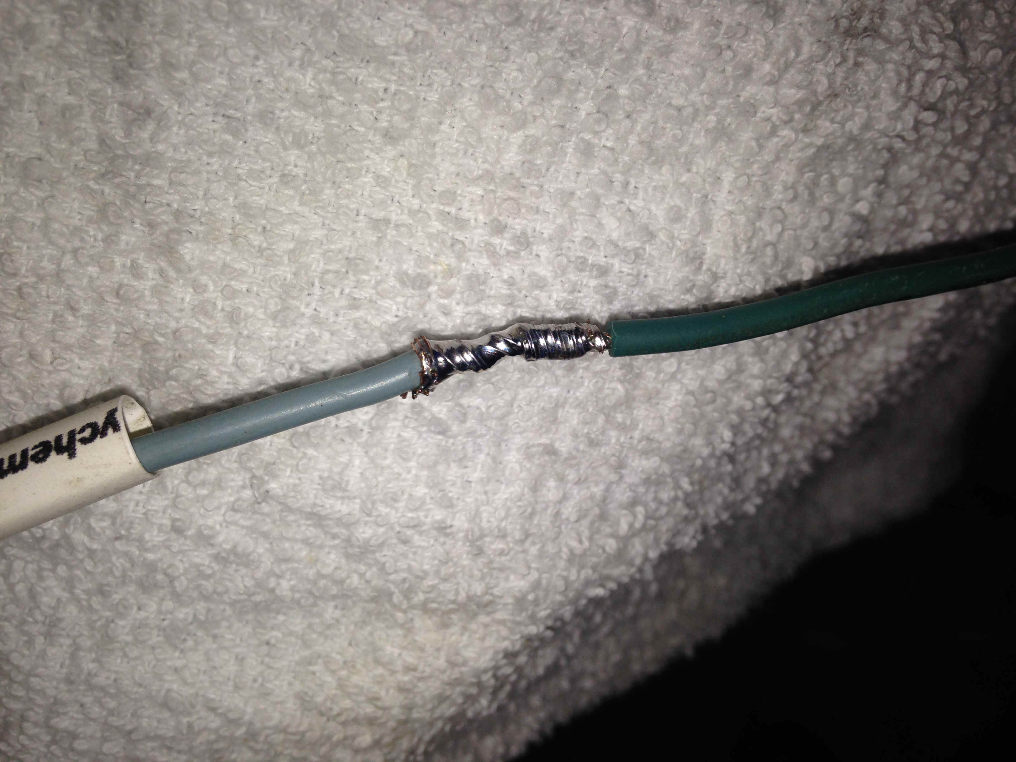
want this... again... watch the videos. There is also a lot of info and videos on crimping. Good tools and good practice will give you good joints... watch the videos and read the data. After the joint is cool again, slide the heat shrink tube over the joint and apply heat... a heat gun is best, but lots of people use a lighter or even the body of the soldering iron... heat guns work best and quickest.. with no fire hazard. Heat shrink tubing is also available in different sizes and prices... buy according to your wire size and don't cheap out. (stay out of dollar daze... you want quality work that will last... spend the money !) I like the tubing with heat activated adhesive inside that seals the joint as it shrinks.. Remember...the smarter you do this wiring, the fewer problems you will encounter later. There is a ton of conversation on the net about crimp vs solder...with good points offered on each side... I like soldered and have never had one fail... but I've also see lots of "properly" crimped connections last for years also.. do your research..... it's your ride. ... now you know how to crimp and solder..., you're ready to be a truck or car wirer person. Here's a look at mine for reference. A good joint should be shiny not dull... dull = cold solder joint and will fail later.. at midnight, on a dark road, in the rain... gauranteed.
|
|||||
|
|||||
| Let's begin...
|
|||||
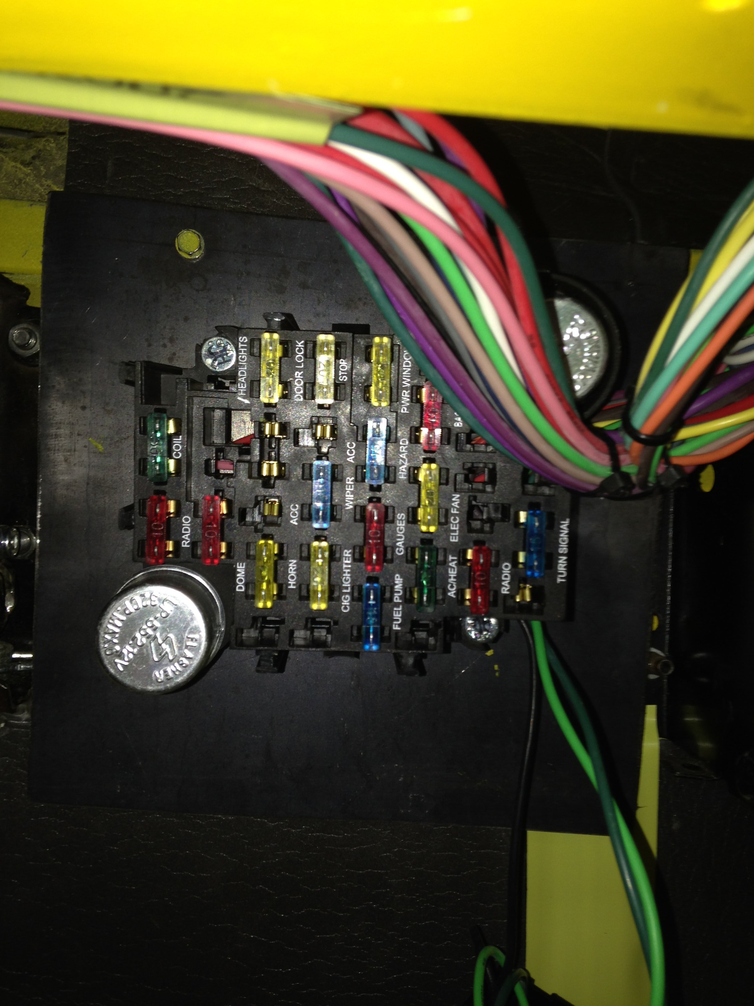
| You have
this tangled up mess of wire all connected to or thru the harness to the fuse panel...
next step is deciding where to mount it. The kit is designed to mount the fuse panel under
the dash to the left of the steering column on the firewall. I'm trying to keep my
firewall as hole free as possible so I built up a crossbar/plate for fuse panel mounting
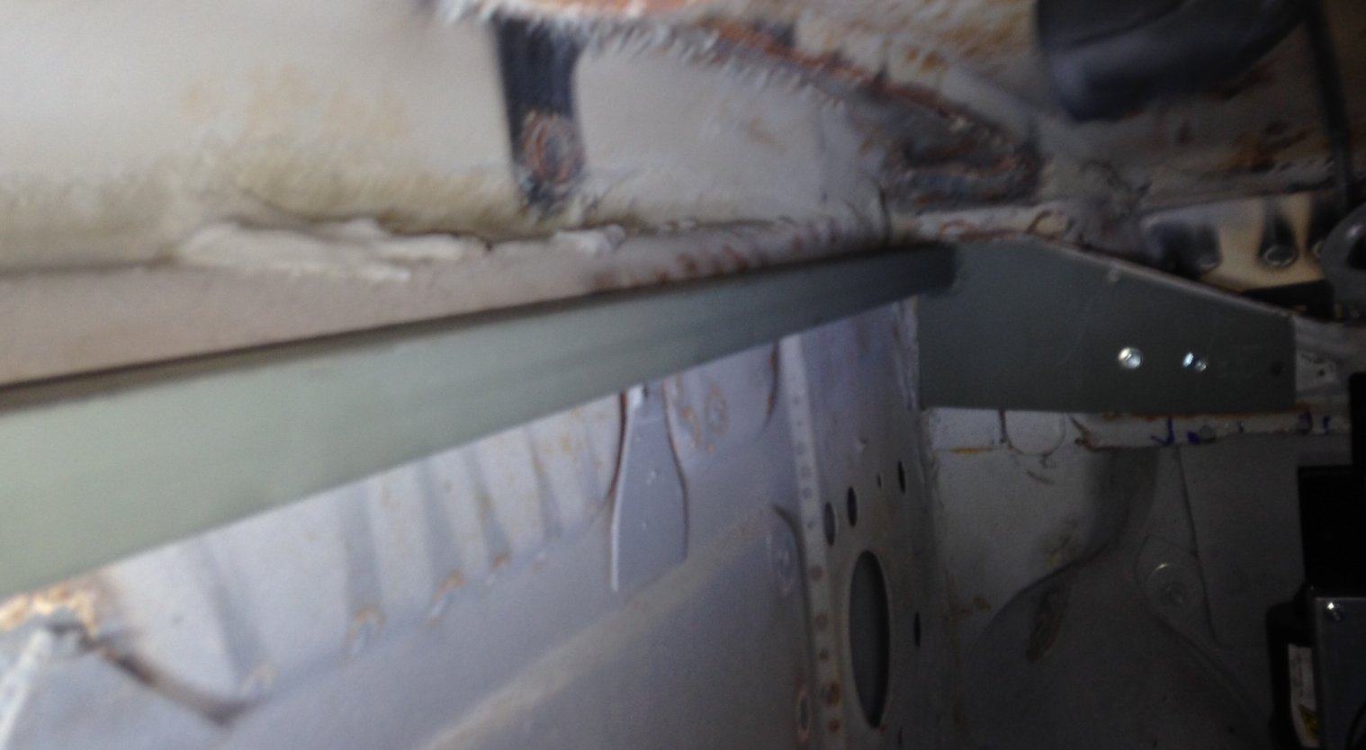
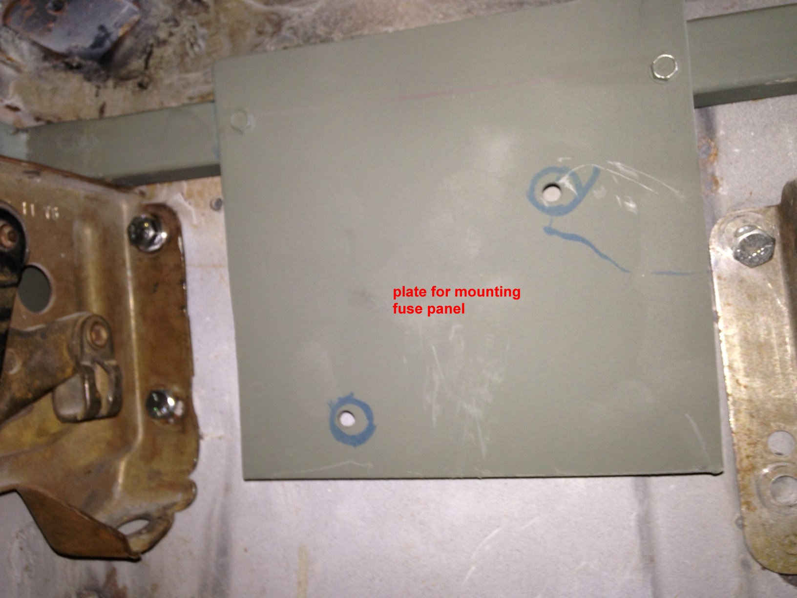
and wire support. It's nothing but a piece of 1" square tubing with mounting
plates at each end that screw to the kick panel braces and a flat plate for the
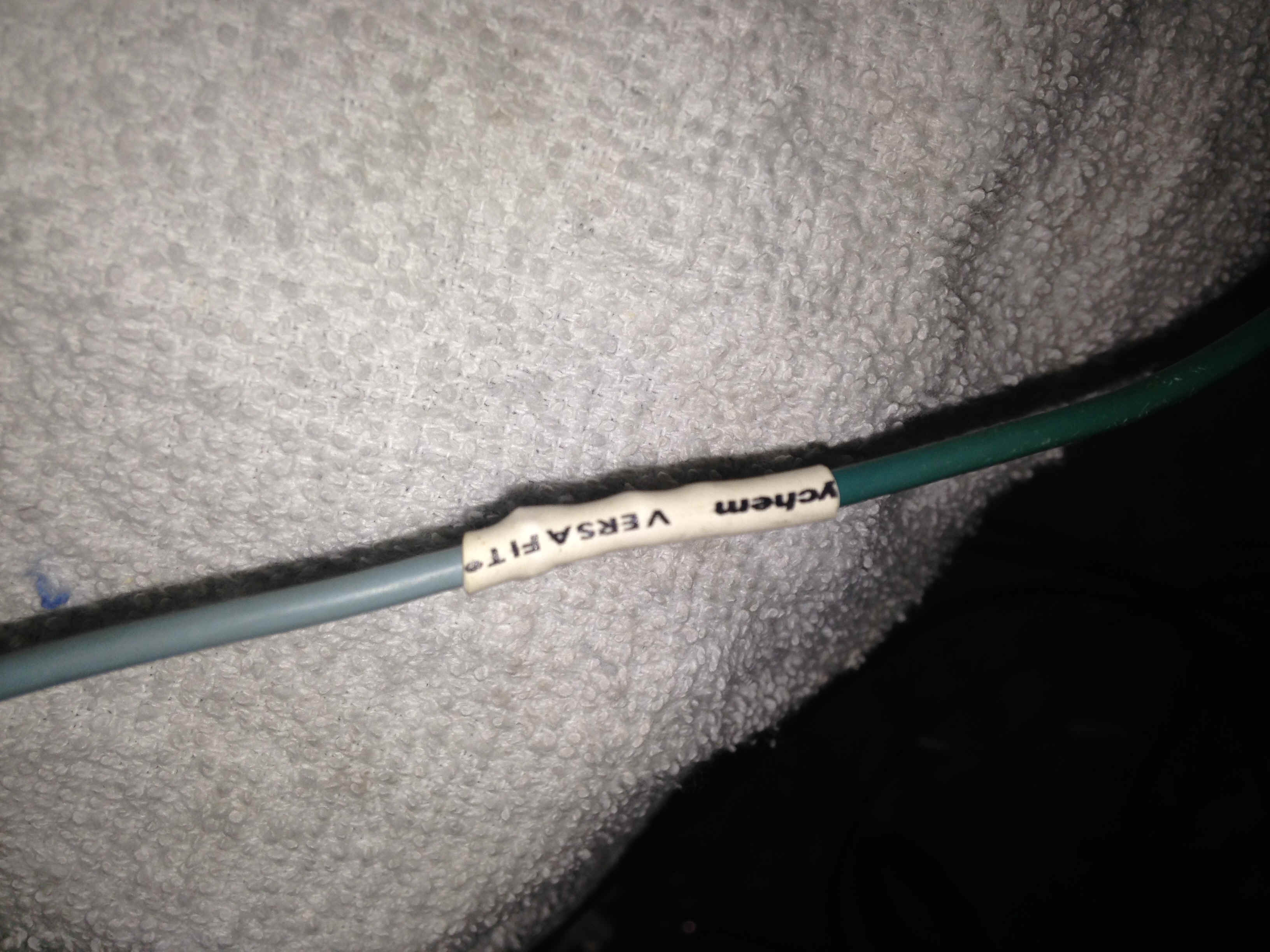
fuse panel. The bar is handy for wire tying the cables up out of the way. The mounting location of the fuse panel can be anywhere you want... under the dash, behind or under the seat, on the firewall even, but keep in mind that the lengths of wire are pretty much calculated from under the dash, left of the steering wheel... if you use a different location you'll probably have to add more wire to certain sections... like headlight and marker wiring up front or maybe out back... just keep that in mind if you get creative with location of the fuse panel. And, if you have to lengthen some put some type of label on the added wire so next week you can remember what it's connected to. Don't ask how I know this.
I got the idea from someone on one of the forums to add a plate/bar that ran across the cab and anchored to the two kick panel braces, from that I attached the fuse panel plate. (No firewall holes, remember?) The plate holds the fuse panel nicely and the bar gives you a nice place to cable tie the harness parts to keep them clean and organized.
|
|||||
| I began the wiring by dragging the whole assembly to the truck and getting the fuse panel in position. I was forward thinking enough to pre-drill the mounting holes for the panel. I mounted the panel on the plate under the dash and kinda moved each bundle toward their final destinations. The front group was stuck inside the drivers kick panel, the rear group was started toward the center of the cab.. the dash panel was left as is and the cab section hung to the right of the column for now. At this point the project seemed somewhat daunting... but it's how you eat the elephant... just take a small bite at a time and complete it. | |||||
|
|||||
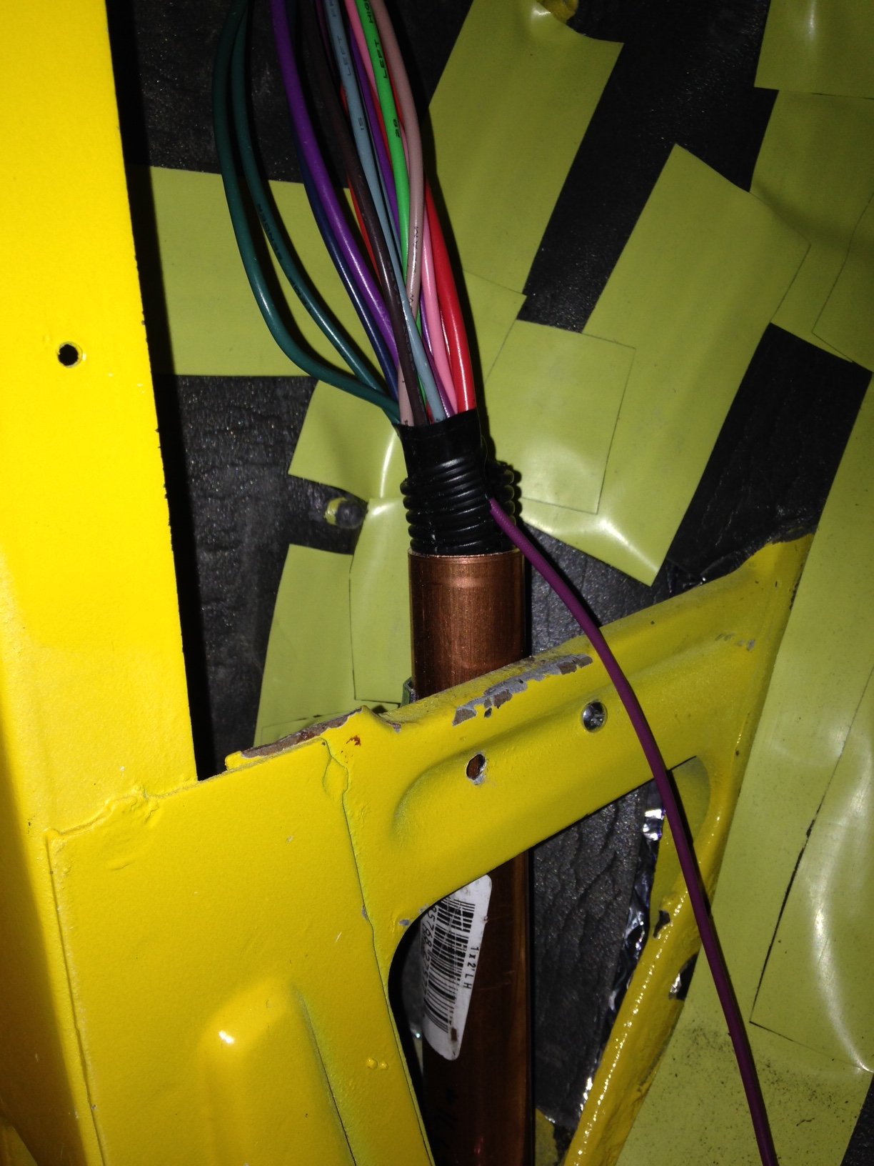
| I decided to start with the front section... NOTE !! if you're going to use the regular firewall bushing and existing hole you can skip this next section on hiding the wiring...Just be sure to insulate the hole with bushing material or grommets and make good connections. The front section really seemed easiest and had fewer wires. As I mentioned I wanted to keep as much of the wiring as un-noticeable as possible so the routing deserved a little forethought. I brought the wiring bundle down inside the kick panel and out through the bottom of the cab. I tried several different 'conduits' (pvc, electrical conduit, water pipe) but with a straight section of 1" diameter pipe and a 90 degree on the end all were too wide to fit in the bottom of the cab corner. I finally found that copper tube with a 90 degree ell would fit. (The copper 90 has a tight radius in its turn) so I soldered up a 1' section of tubing to the ninety, drilled a 1-1/8" hole at the very bottom of the cab and stuck it in... it was a perfect fit and the 1" tube was large enough to hold all the wires for the front section. I used a pipe clamp to hold the tubing in place at the kick panel cross brace. I deburred and radiused the ends so there was no sharp edges on the leading edges and then I used a 2" or so long piece of the convoluted wire loom for a bushing at each end of the tubing to prevent chafing and cutting the wires. | |||||
|
|||||
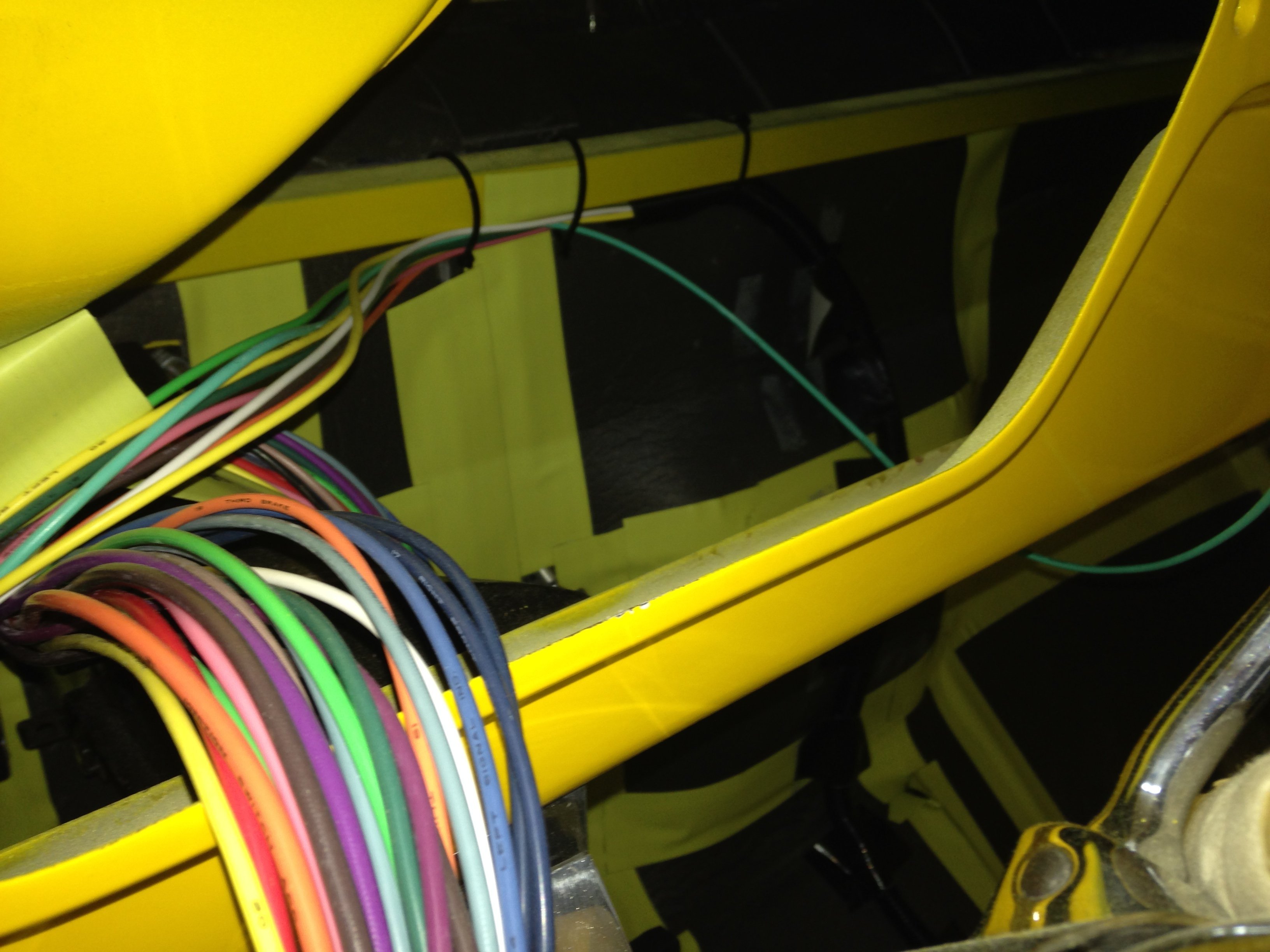
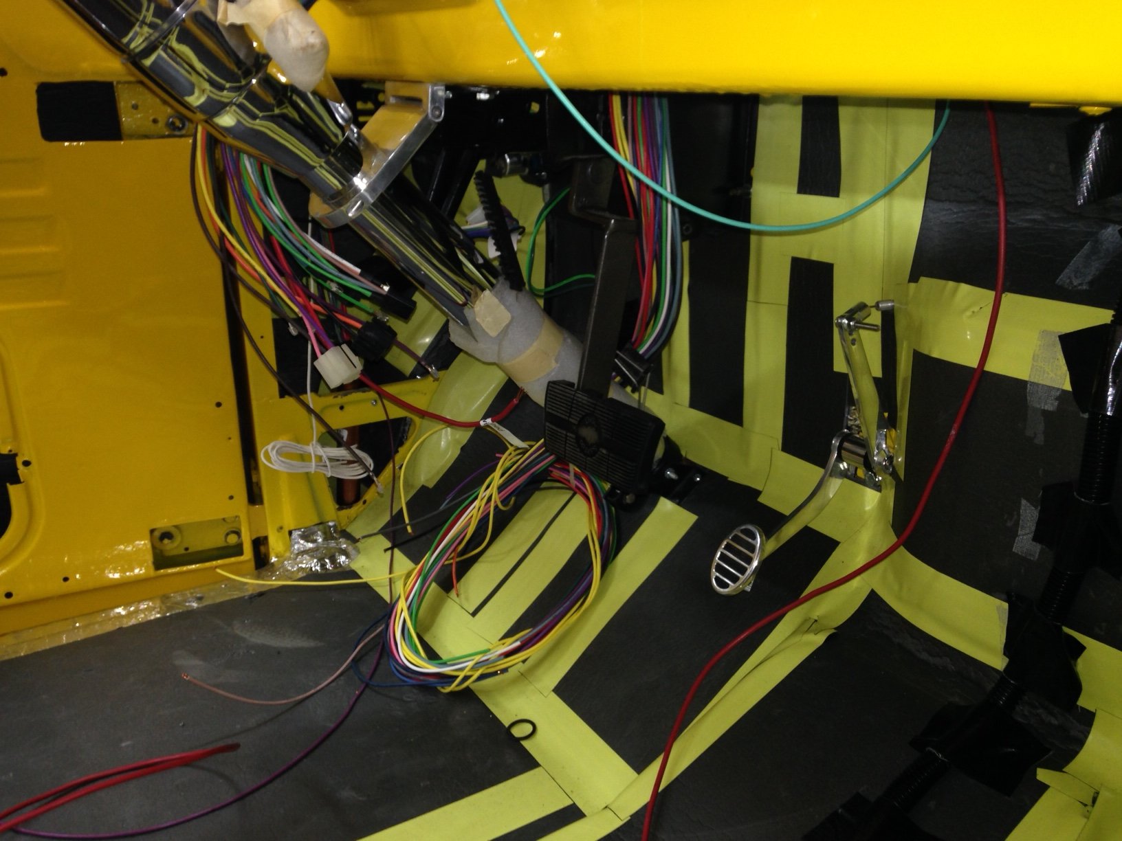
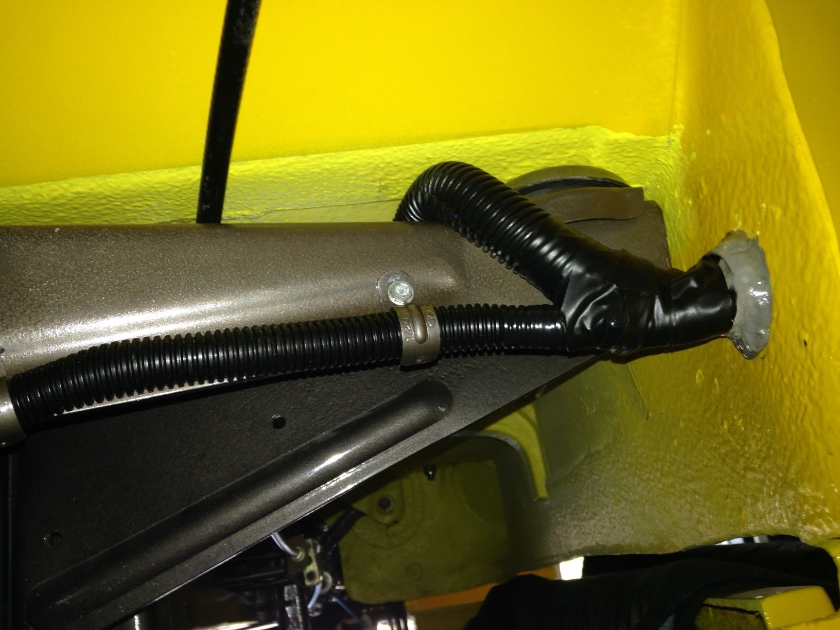
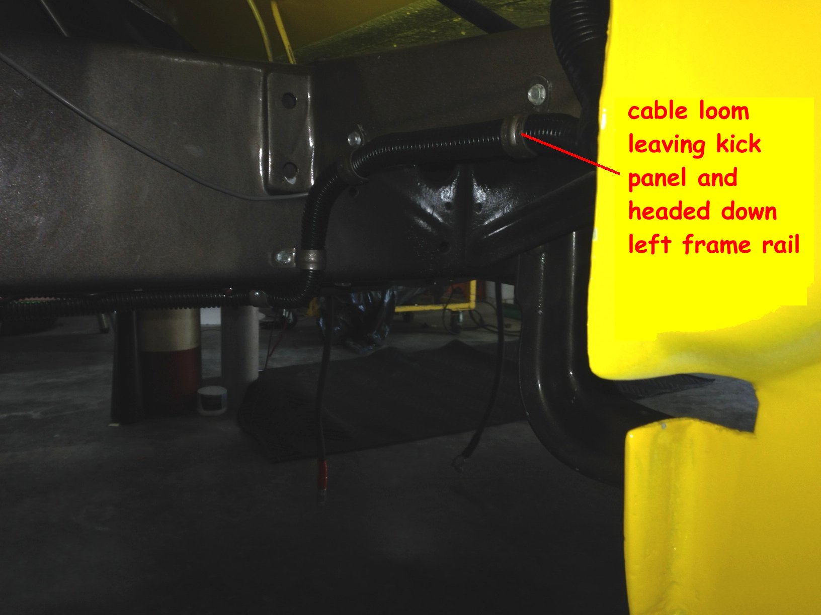
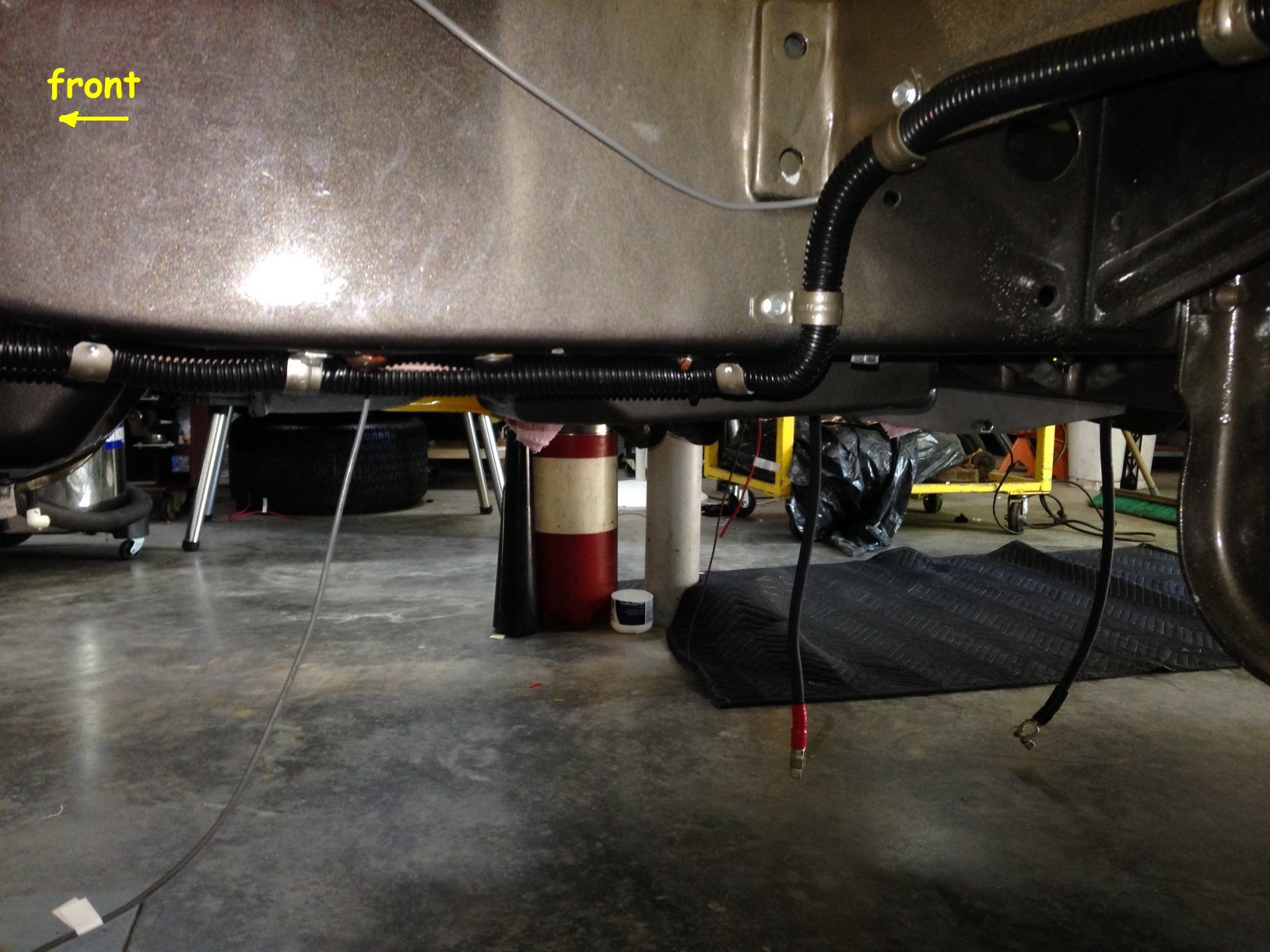
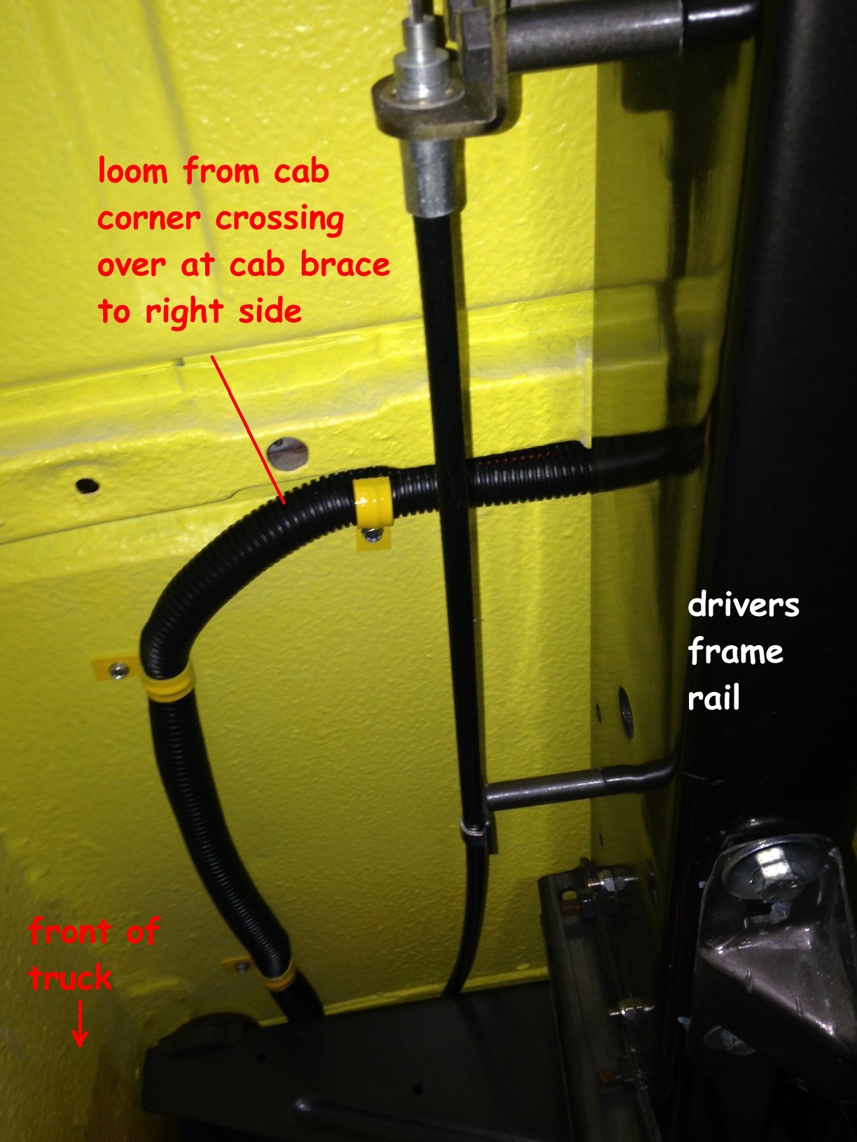
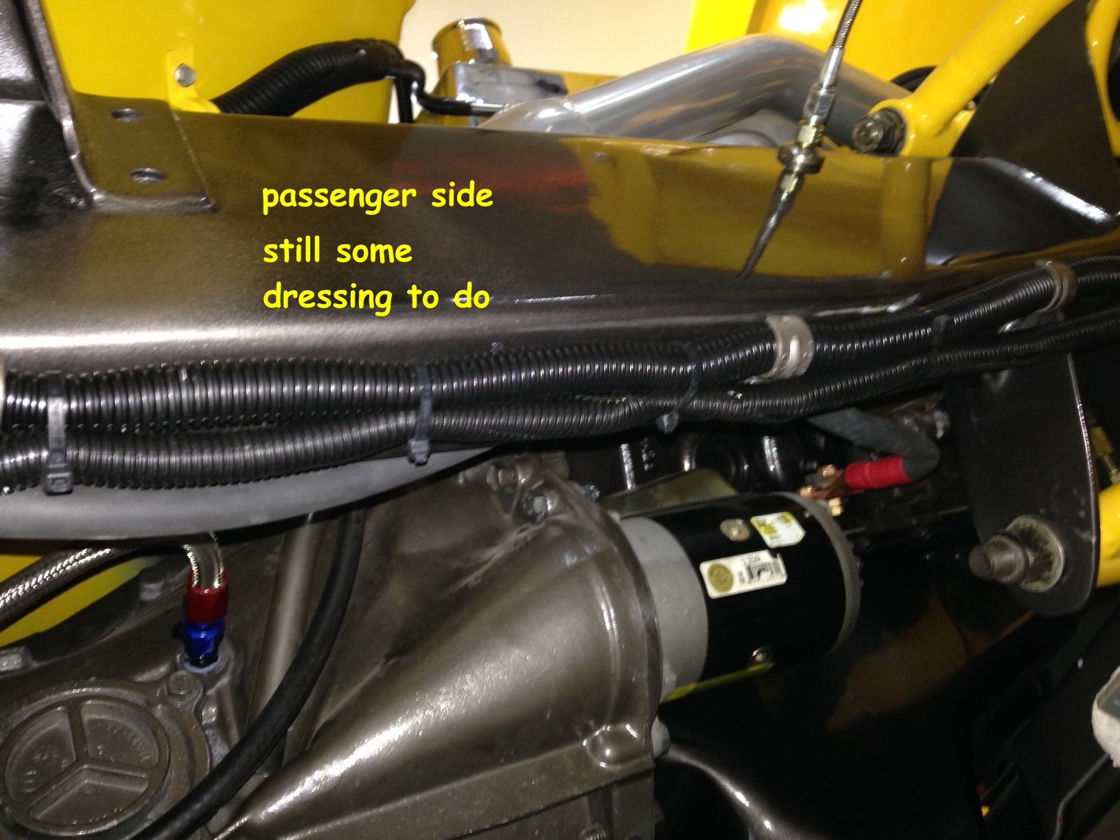
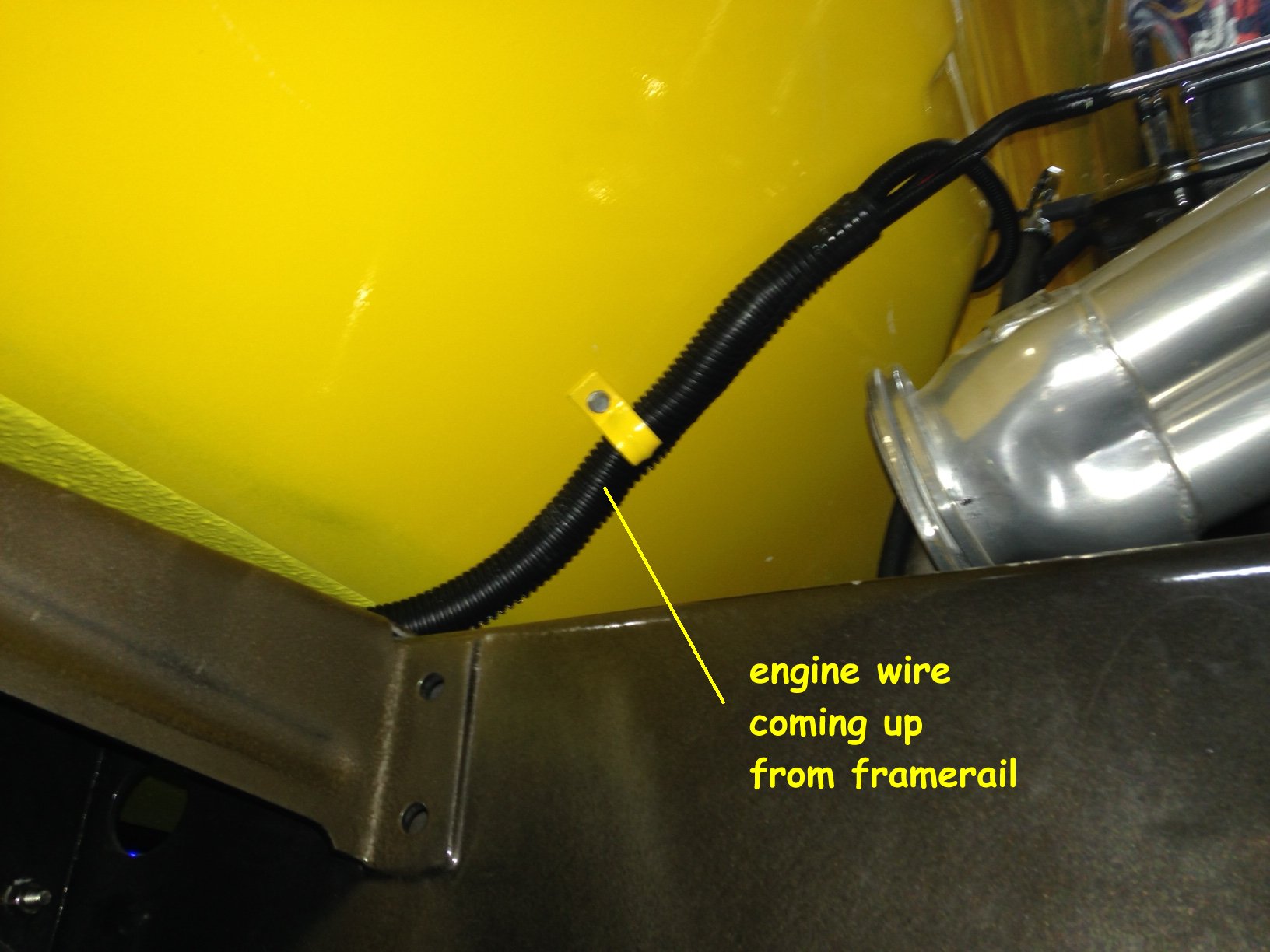
| You can
see the picture below where the wires come out of the lower cab.. from this point they
split off to different directions. The horizontal loom you see runs over to the
drivers frame rail and is clamped down the length of it to the front. The loom going
over the cab mount actually goes to the passenger frame rail and then onto the
front. Lots of folks run the wiring inside the frame rail to hide it or clamp
it to the inner fenders ... with a tilt hood there are no inners and everything is exposed
to yo necked eye... the front half of mine are boxed so everything is exposed.
I tried to loom everything and run it under or behind the rails to keep it as hidden as
possible.. Only those crazy people like me will get down on their hands and knees and see
what I've done and that's ok... their knees will be dirty. Here's some misc
pics of the routing.
|
|||||
|
|||||
|
|||||
|
|||||
|
|||||
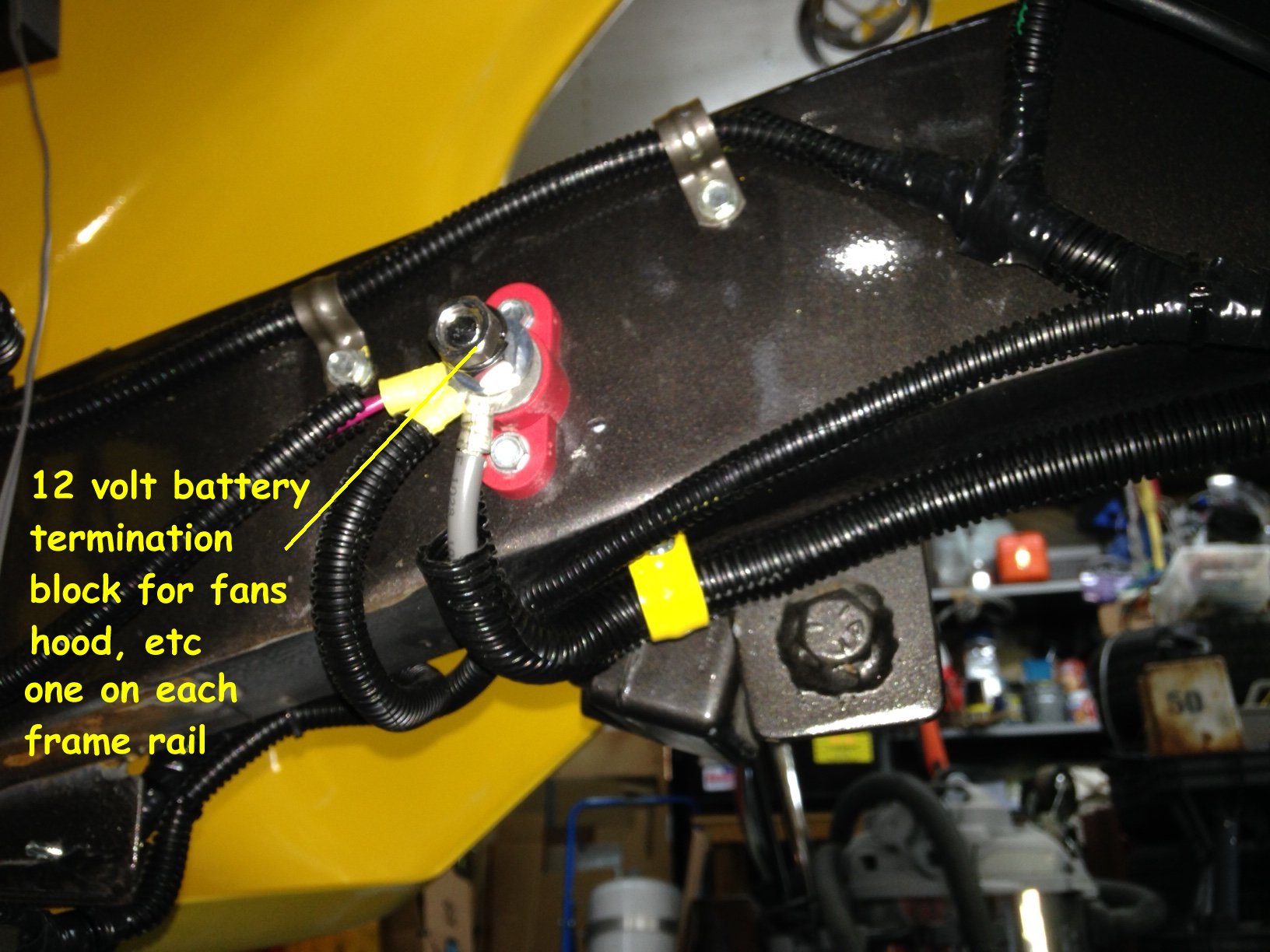
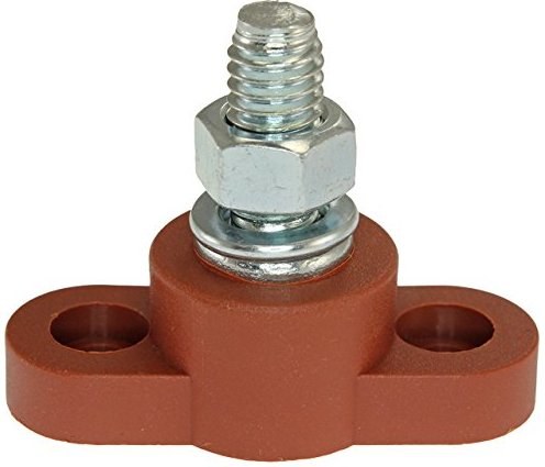
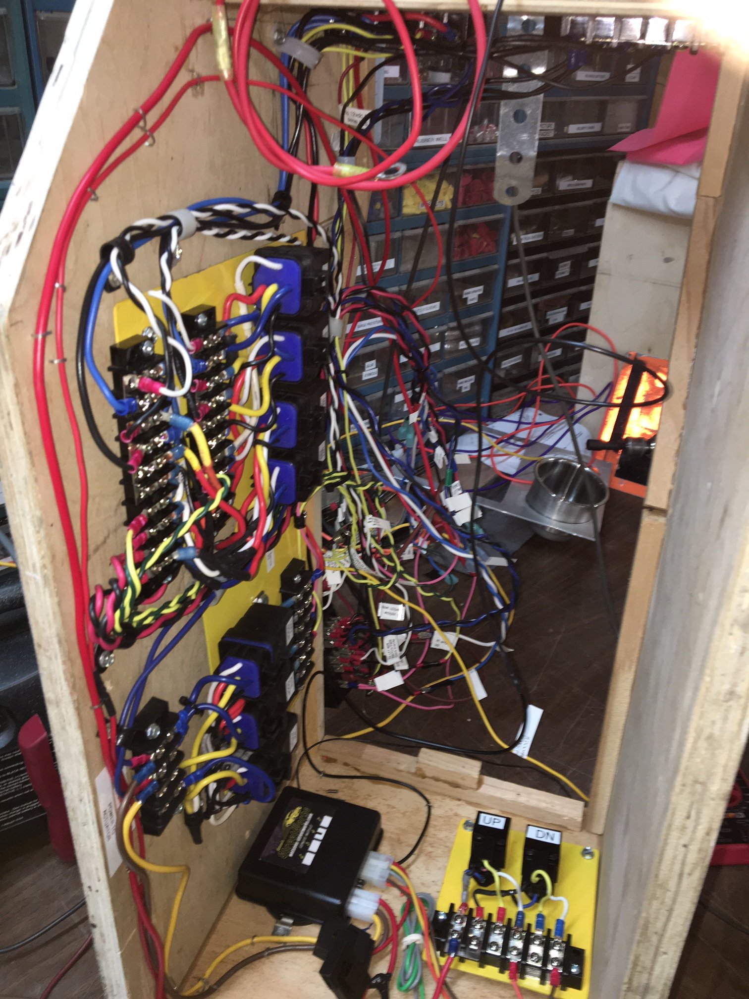
Relays There are some hi-amp draw places up front... Headlights, fan and tilt hood. Relays will be used to control these. That way you can keep the heavy cable runs short (from the battery or a termination point) and the switching wires can be light gauge back to the cab. I mounted two 12 volt battery voltage termination blocks inside each frame rail up front (seen above). Drivers side controls the hood and lighting circuits and the Passenger side controls the fan. If you are not familiar with relays and their function you can read this for some basic detail and fun facts...http://jniolon.classicpickup.com/relays/usingrelays.html. Pay attention, there might be a pop quiz later. Note... I mentioned before about quality components... the same applies to relays. Good relays don't cost much more than cheap bargains. Look for name brands. You should buy a name brand unit from suppliers with a good reputation like Waytek (waytekwire.com) or Digikey (http://www.digikey.com ). There are several behind google. The same goes for fuses ... stay away from Harbor Freight and other import stuff. Use Buss or Littlefuse. An alternate source is OEM relays from the salvage yard. Next trip Ior make a trip) and snatch a few out of the fuse blocks there... if they don't just give them to you they won't be much. They are usually very good quality relays.
|
|||||
|
|||||
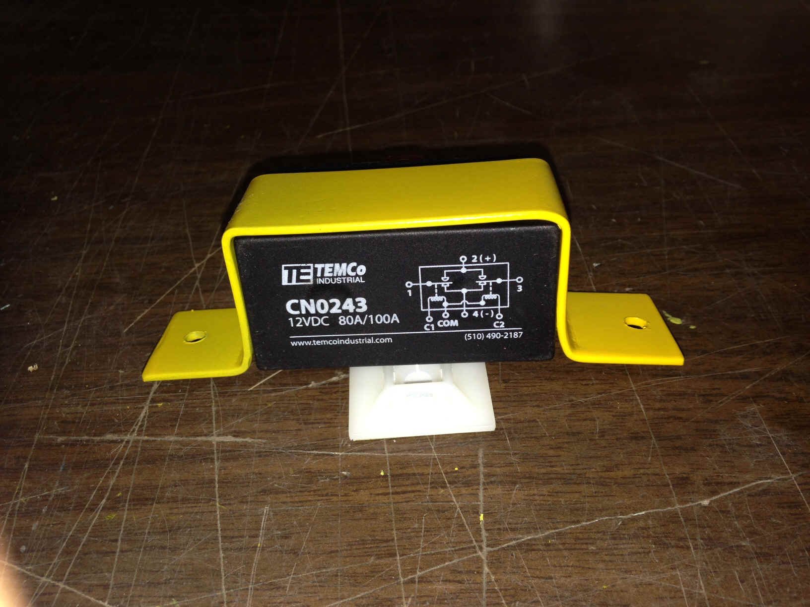
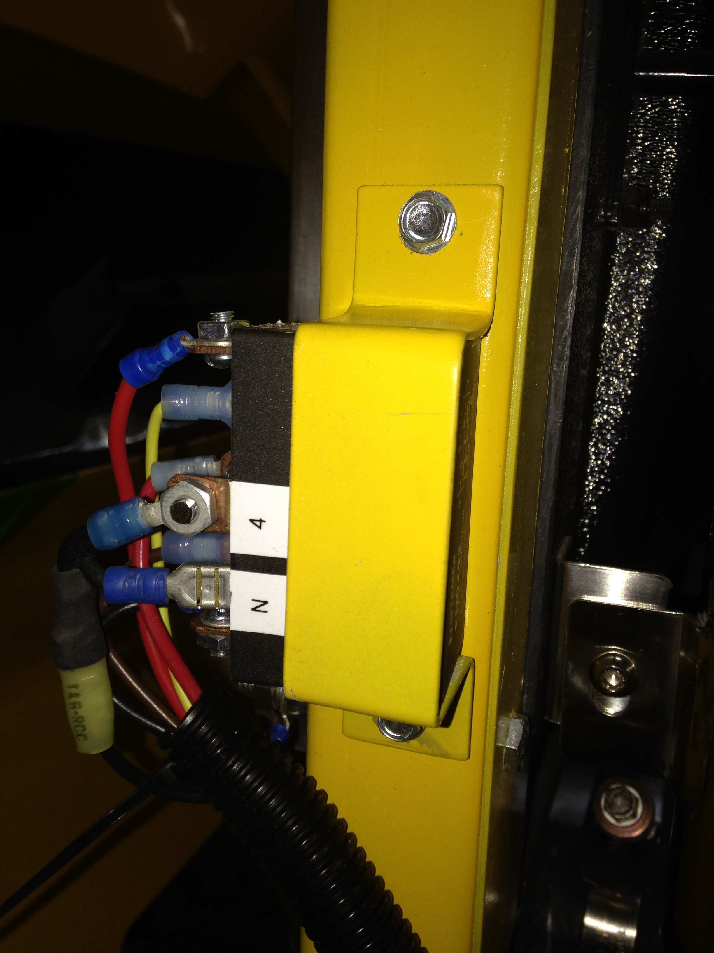
| The
relay for the hood actuators is a solid state 100 amp relay that powers both
actuators. It's way overkill but built like a brick, waterproof and
dependable. Here's a pic of the mounting on the radiator support.
|
|||||
|
|||||
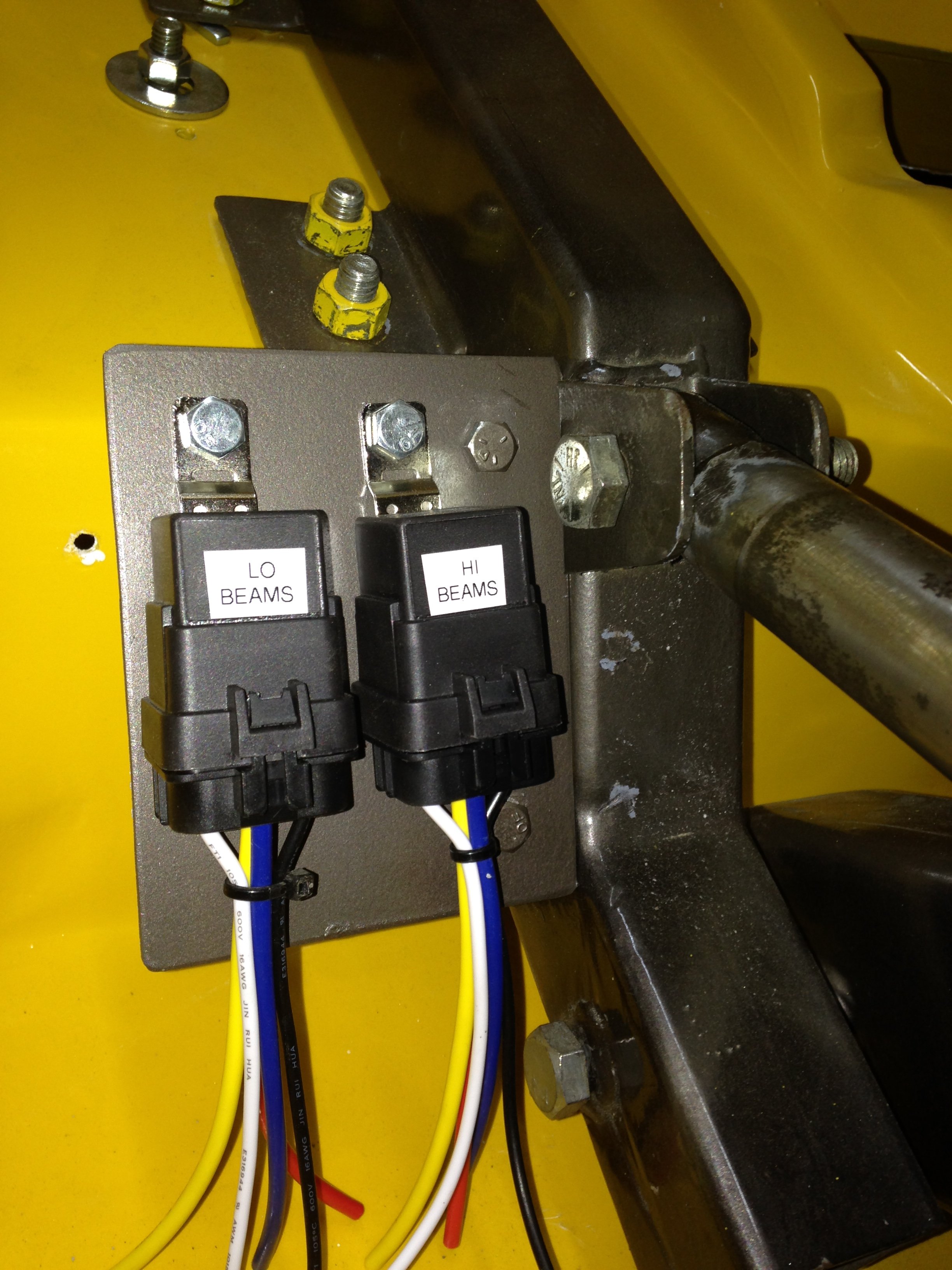
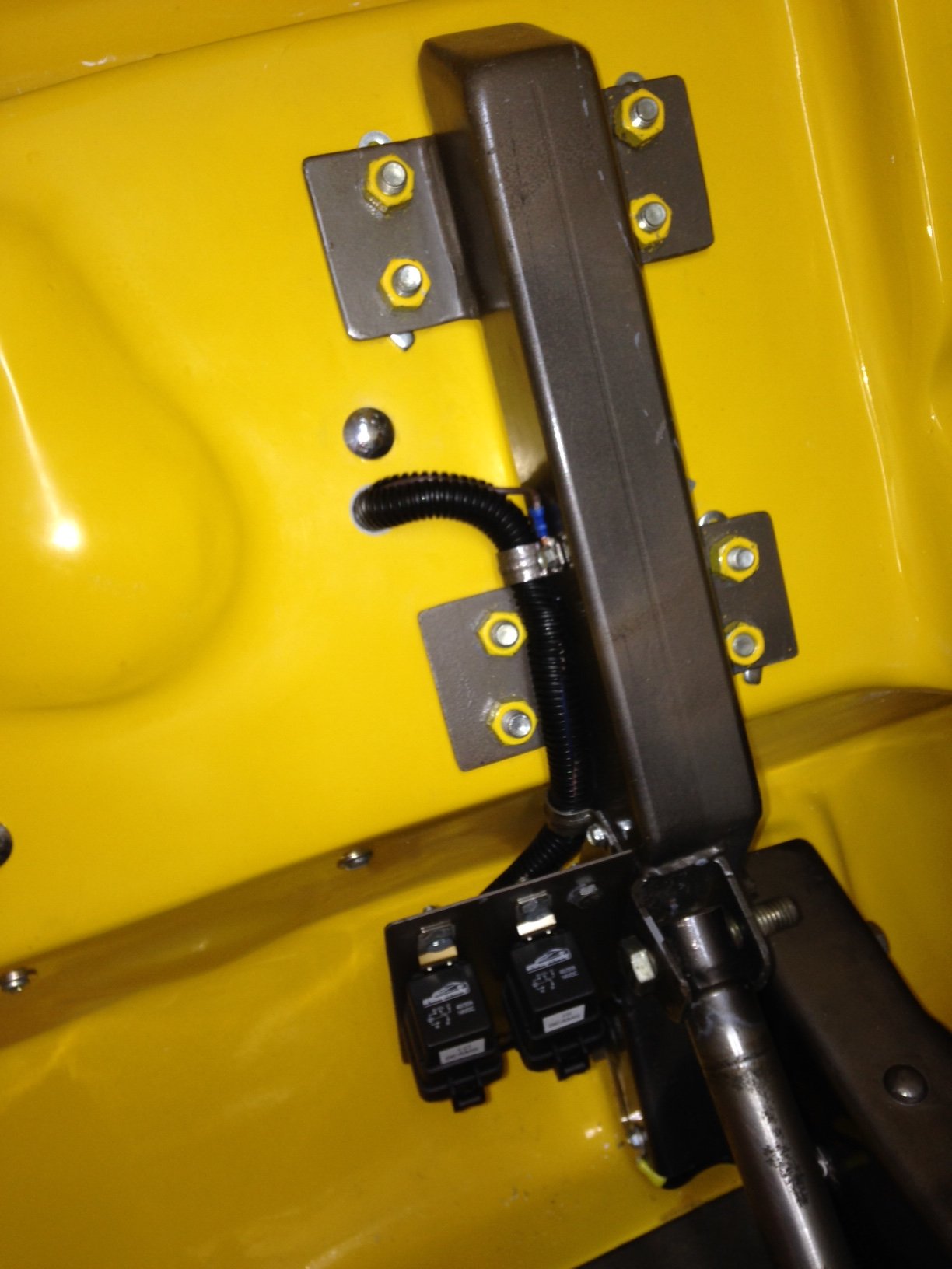
| The
headlight and signal wiring is terminated on a relay board mounted to the tilt arm.
Even though I don't plan on driving in the rain if possible.. since the relays are
exposed, I used waterproof relays/sockets. The difference in price was little.
One relay for hi beams and one for low... then the output of the relays is passed
through the air dam to the grill.
|
|||||
|
|||||
| The
headlight buckets were mounted and the sockets for the bulbs were added to the
wiring. the turn signal and parking light wires left the bucket and went down to the
light assemblies... all in loom. I did the left side first and trying to keep with
the hidden wiring I ran the right side loom across and behind the lower bar of the grill
and finished the wire up there..
|
|||||
|
|||||
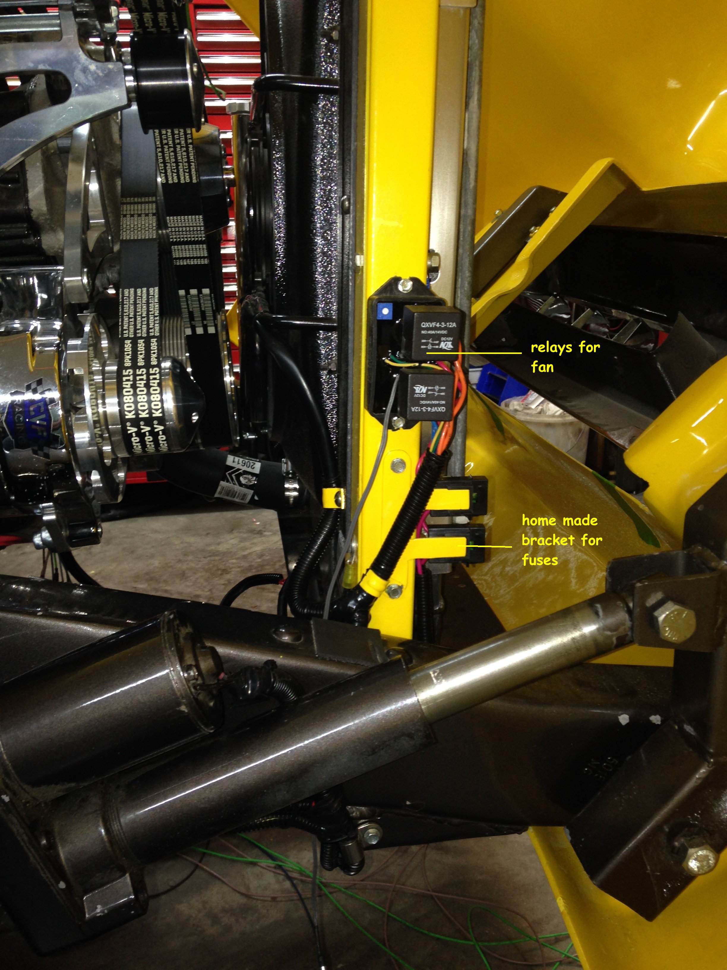
| The fan is a Cool Components unit and uses a set of relays/fuses that they provided and I mounted them on the right radiator frame. Power came from the 12 volt termination block on the passenger side. There is also a wire for 12volt switched power which keeps the fan from running while the switch is off... it goes back to the terminal box under the cab. | |||||
|
|||||
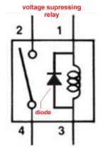
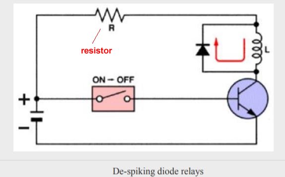
| Note... Although most 'old truck' circuits just need to see around 12 -14 volts dc, some of us might add some sophisticated electronics, stereos with amps, gps, cameras and video displays, charging ports for phones, etc. Relays switch power in a great way, but when the coil 'de-energizes' and the contacts break contact, the magnetic field of the coil can produce a voltage spike. High voltage/low current. Now it won't hurt the horn or the window motors but can maybe not play nicely with some electronics. Relays are made with a diode or resistor that bleeds off or blocks that spike and protects the circuit and it's end user. They are referred to as voltage-suppressing or despiking relays... Diodes are used paralled to the coil and block the spike or resistors are in series with the coil and bleed off the spike...both doing the job in different ways. You can tell if you have that type relay by looking at the diagram on the case which will show the diode or resistor in the circuit. | |||||
|
|||||
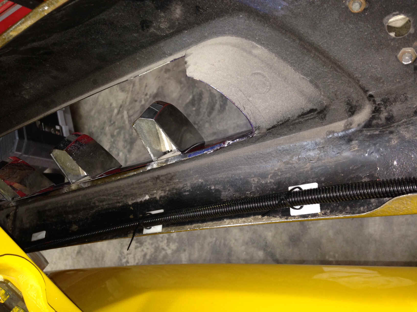
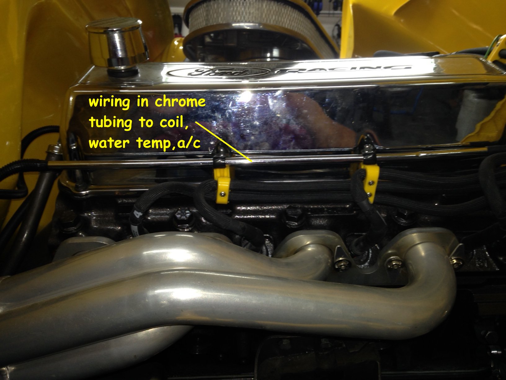
| The
other wiring needed in the front was for the oil sending unit, water temp. sender, a/c
compressor, tach and distributor. The picture below shows the valve covers and a 3/8" chrome tube running parallel with the cover. I ran all the wiring for sending units, dist. and compressor thru these, drilled the tube at each exit point (turning the drilled area down to hide it) and finished them with loom to each device. I brought each section of loom up to the tubing and attached it with heat shrink tubing to keep it in place, same thing where the wire exited the tube and went back to loom... |
|||||
|
|||||
| With a little clean up and loom clamping the front section was finished... one exception is a horn. I'd really like to find something special (think train horn) and the mounting location and wiring will depend on what I come up with. Edit... have found a set of Cadillac 4 note horns. These sound amazing. Seperate article on the install https://jniolon.classicpickup.com/horn/horns.htm | |||||
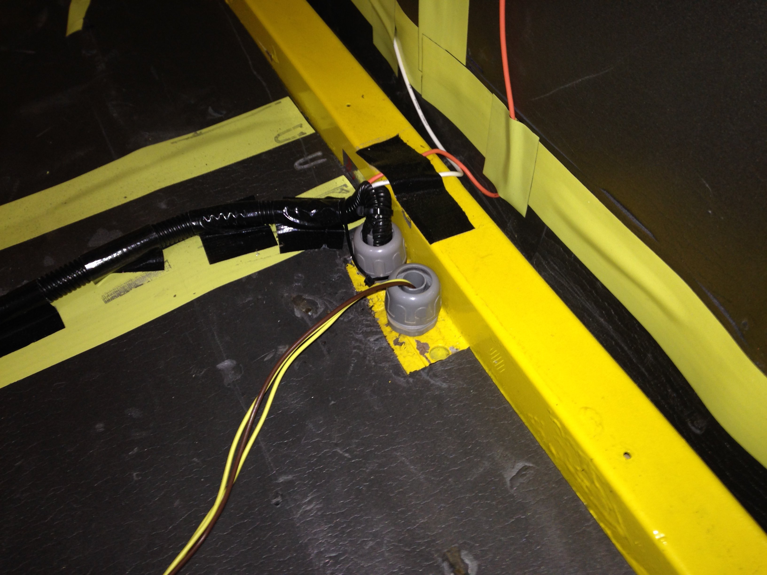
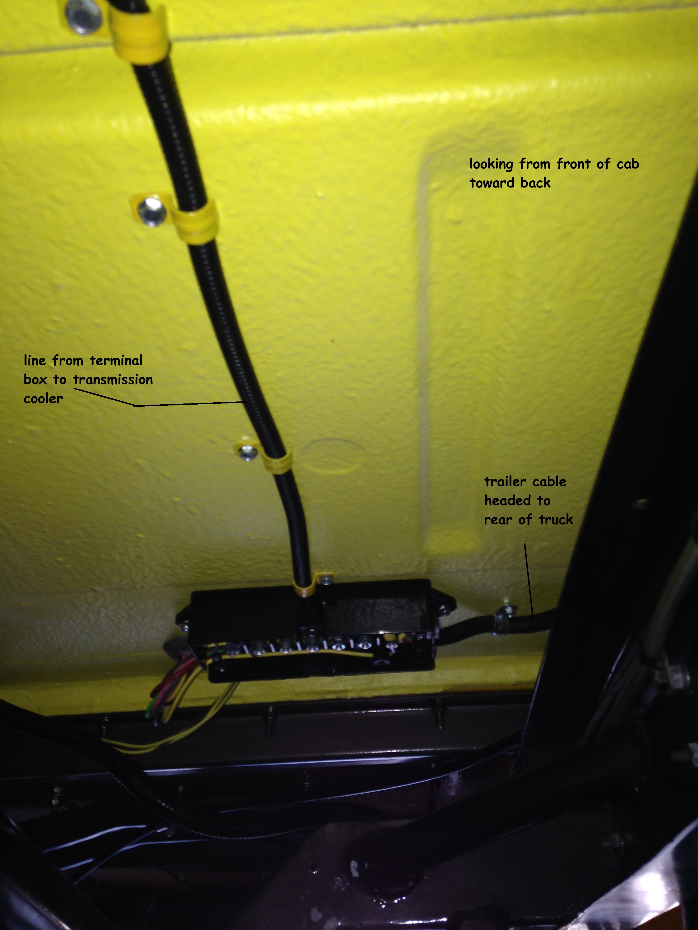
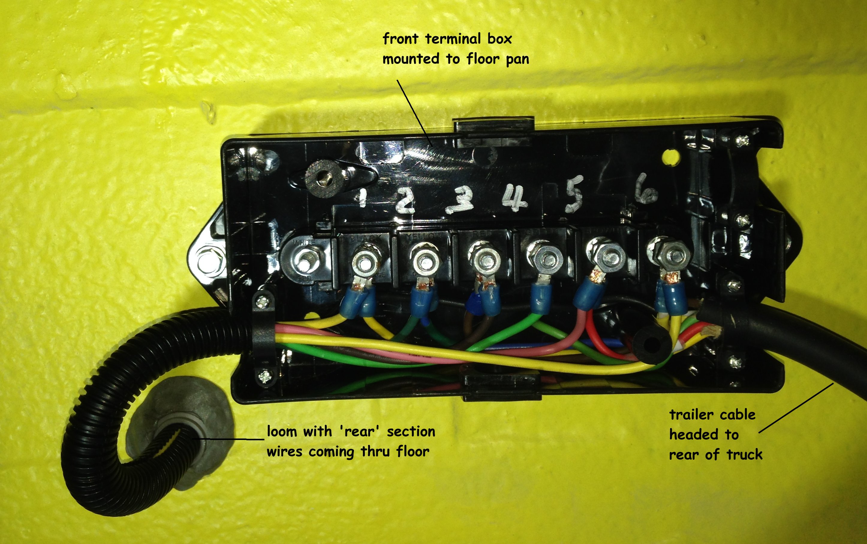
| The rear section wasn't a bad chore either. I brought the rear section wiring group over to the center of the cab (inside) and down the firewall, across the floor (which will be under the console.) Then I used waterproof flexible conduit fittings to go through the floor to the first box...A fellow ford lover suggested using 7 conductor trailer wire to get to the back instead of using individual wires to each component... sounded a lot easier and neater... I bought two terminal boxes used for trailer wiring off e-pay and here's what I ended up with | |||||
|
|||||
|
|||||
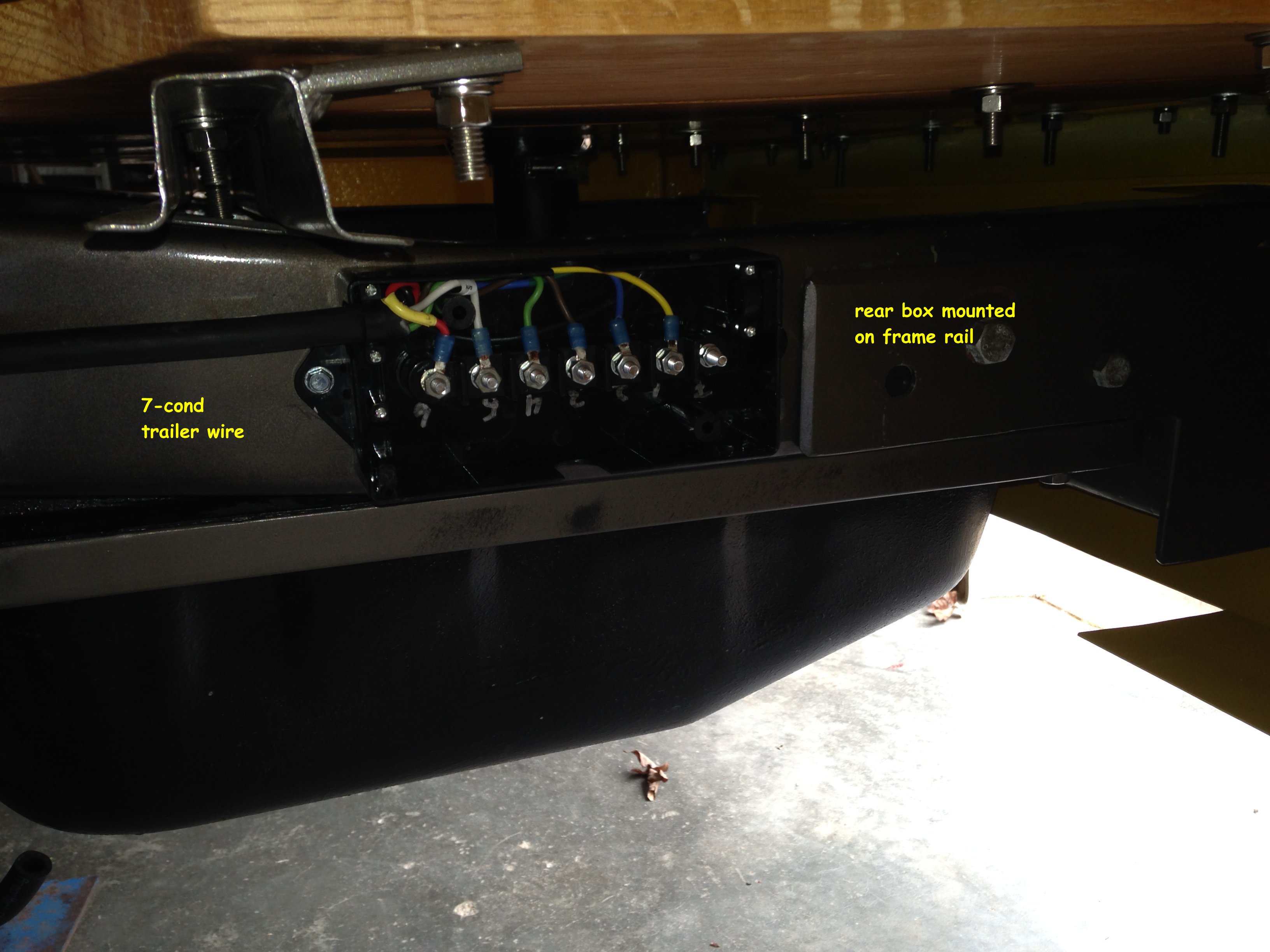
| from the rear terminal box I used the 'rear' section wiring I had cut short at the front box and continued from the rear box to the tail lights, tag light, etc... all in plastic loom and secured to frame with clamps. That pretty much finished up the rear except for the fuel sending unit., I haven't reinstalled it yet. Dolphin Gauges recalibrated it for their gauge set .. There will be a lead from the rear terminal box to the sending unit... and the other end is still in that rats nest at the dash. | |||||
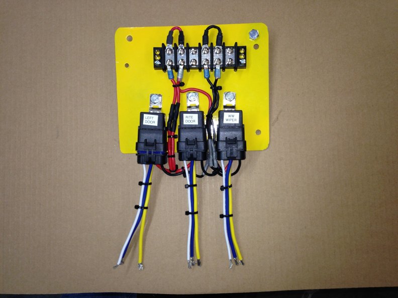
| Cab
section comes next... my education continues. I've got several areas that need
relays to operate. Door opening latches solenoids, wipers and windows.
The door and wipers are easy enough... the doors are momentary on/off switches that
activate the solenoids and pull the latches open... the wipers are on/off also but a
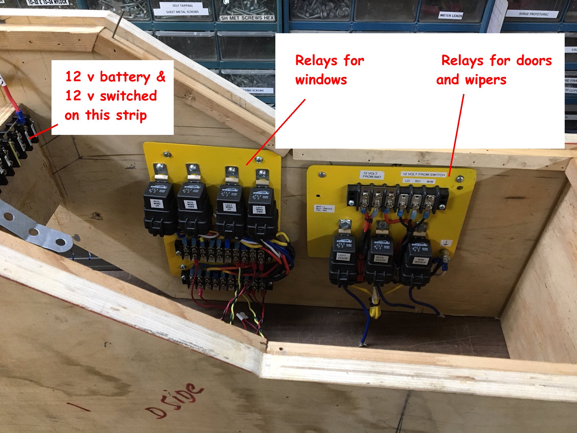
standard switch. I made up the relay board for these like this
|
|||||
|
|||||
| they
will be mounted under the dash with the leads for the door switches headed to the console
and the wiper switch leads going to the switch in the lower dash panel. These were
the easy ones Edit... look below
for additional door remote access information
|
|||||
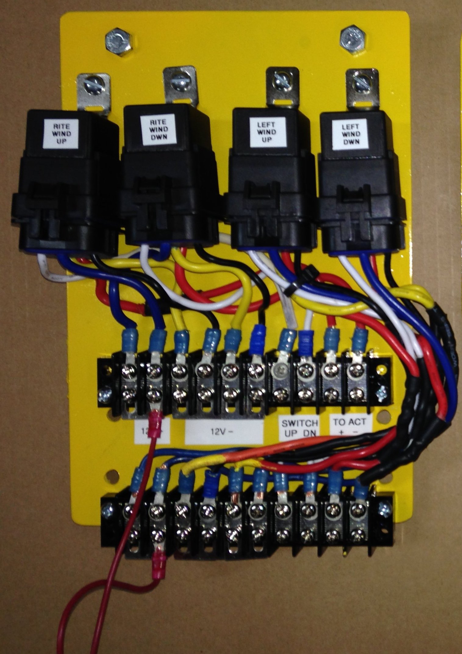
| The
window switching was a little more complicated. First of all my window kit came with
no instructions and the vendor was long gone. Called around and could find nothing
about the manufacturer. the switches and wiring were in the box with nothing to tell
me what went where... So I started from scratch. That's what you get for buying
stuff and waiting 10 years to put it in. The window motors are DC (of course) and work by switching polarity to the motor leads. The motor is isolated from frame ground. I had to come up with a circuit that would do that and not be grounded to the truck. Took a lot of searching... at least for me but I finally found a circuit using two separate relays to do just that. The drawing was a little confusing and had an extra 'dot' in it but it did work properly
|
|||||
|
|||||
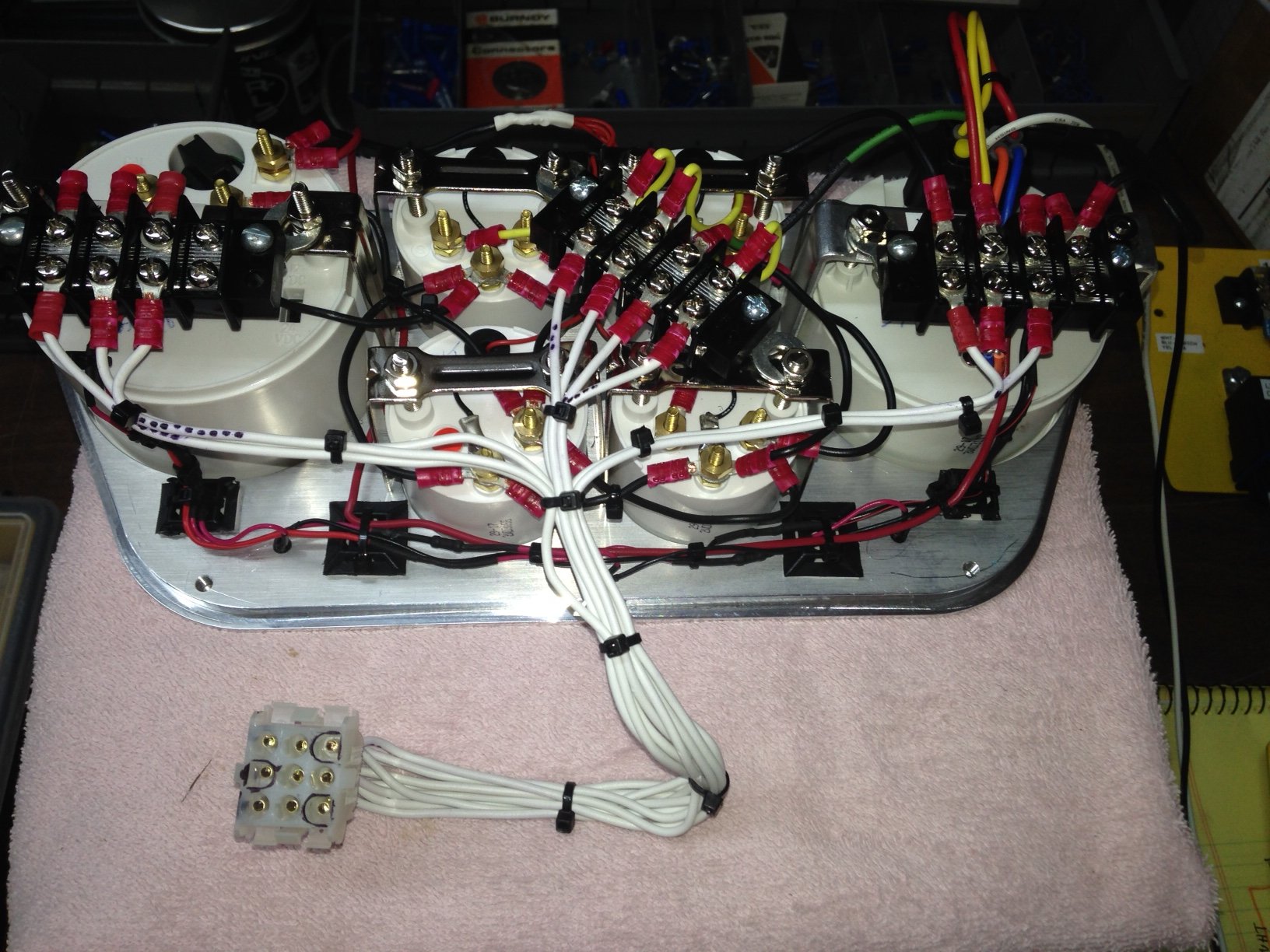
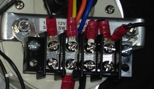
| So, for both windows it took four relays and a couple of 10 point terminal strips to handle the mess of wiring. I wanted to try it out before building it so with switch, relays, battery and about 15 jumper cables I hooked it all up. When I pushed the up switch I got positive 12vdc on one lead. When I pushed the down, I got negative 12vdc on the same motor lead... Eureka !! I'll duplicate the circuit for the passenger side window. Now I just have to build it. Under the dash is getting a little crowded and I still have to add a/c unit, hoses, tubing and more wiring so I think these relays will mount inside the console. | |||||
| Here's the final product... someone with more knowledge and talent could have done it better, but this works... it will mount inside the dead space in the console. | |||||
|
|||||
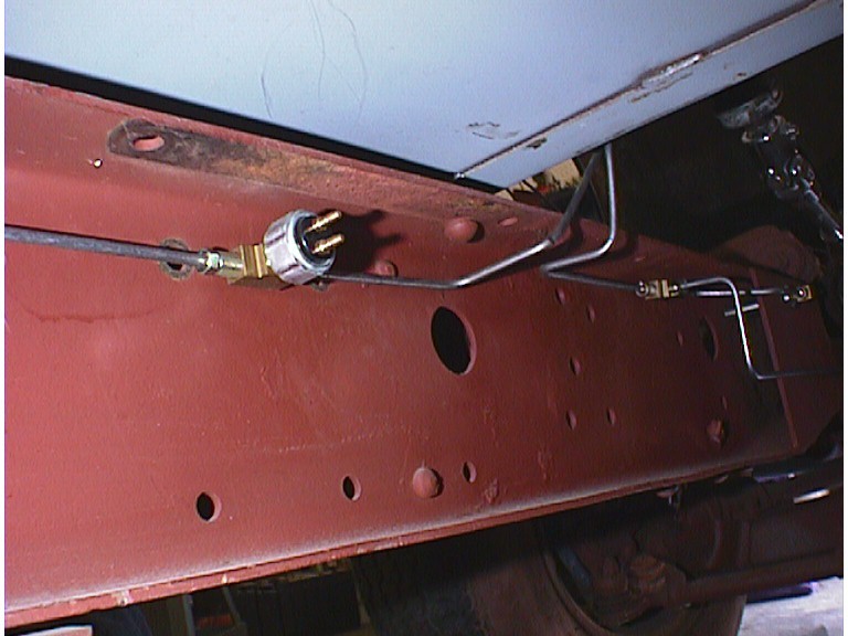
| At this point I started thinking about some things I had left undone . The brake light control switch, the backup light switch, the neutral safety switch, etc... I had basically just run the wiring from point A to point B and decided to work on the middle later... well, it's later. The brake light switch is a pressure switch mounted in the brake line | |||||
|
|||||
| Brake light wiring is brought from the harness to the switch by two wires. The brake power and return wires are not documented in the instruction manual or on the limited drawings. I finally had to call the techie guy and ask. It's simple..one wire on each pin on the switch. Then from the column wiring to the light circuit itself... the switch is basically a n.o. switch that is activated by brake system pressure to close and complete the wiring circuit to the brake lights | |||||
CORRECTION
|
|||||
| There's
been a change here but I thought I'd leave the original plan (above) in the article to
show the difference. Initially the inline pressure switch was the choice but that
was before the brakes were tested.. Once I filled the brake system and bled the
brakes I noticed the switch 'weeping' brake fluid.. figured I had a bad switch and changed
it out... it leaked also... as did the third switch !!! I needed another
solution.
|
|||||
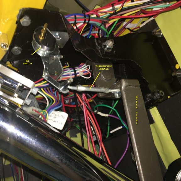
| Bought
two switches., one from Speedway, a universal switch and a Keep-it-Clean version... Both
work identically... and opposite of what I thought they should. They are spring loaded and
in the 'resting' position the switch is open... the brake lights are off.. As you move the
lever the switch makes contact and the lights come on. To me that meant the switch had to
be in front of the brake pedal so it could pull the lever. I mounted the switch to a 90
degree bracket and then screwed that bracket to the brake pedal framework under the dash. Then for a couple of hours I tried 13,450 different combinations of springs, chains, wire, rods, brackets, combined with lots of expletives and a sore neck from laying under the dash. My Problem was that I couldn't get the switch to "on" itself where I wanted it too. Finally the brake circuit gods dropped a wrench on my head and I came up with the idea of using a turn buckle. WA- LAAA!!!. Infinitely adjustable, stable and strong. Now to 'unplumb' the hydraulic leaker, bend another tube to add an inch to the line and bleed again... oh, and reroute the switch wiring from under the cab to under the dash...
Here's a link to the article on the brake light switch http://https://jniolon.classicpickup.com/brakes/installingamechanicalbrakelightswitch.htm |
|||||
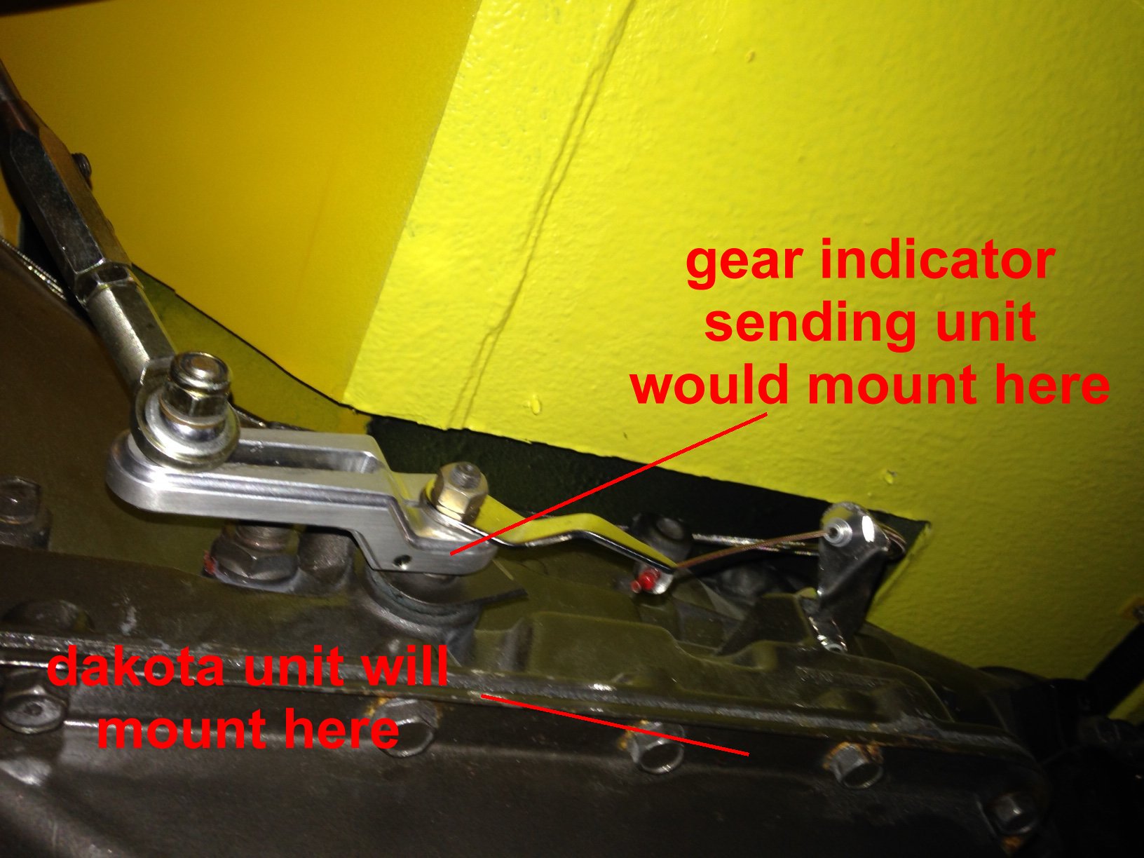
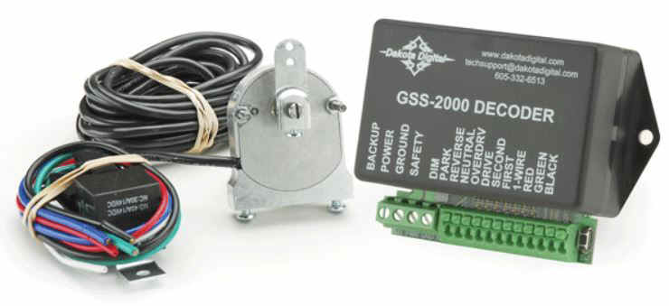
| I
stumbled a little on the neutral safety switch, The OEM units mount on the side of
the transmission on the shift control arm but my Lokar linkage had already taken that
place..
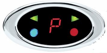
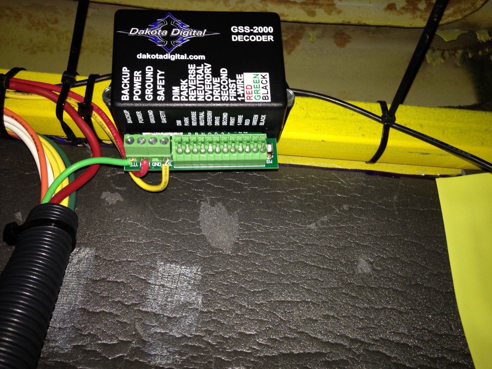
A little research and queries on the FTE forum led me to an aftermarket unit made by Dakota Digital solved several problems at once, it had a sending unit that mounted to the transmission pan and used an arm that converted the shift linkage position to a digital signal that gave the correct readout on a separate panel at the dash. It also handled the neutral safety switch problem and the backup light switch. I decided to put the readout in the column drop but didn't have the tools to mill it out nicely. Took it to a friend with the equipment and he hogged out an oval hole perfectly for the readout... had to do a little re-polish on the drop but it turned out nicely.
|
|||||
|
|||||
|
|||||
|
|
|||||
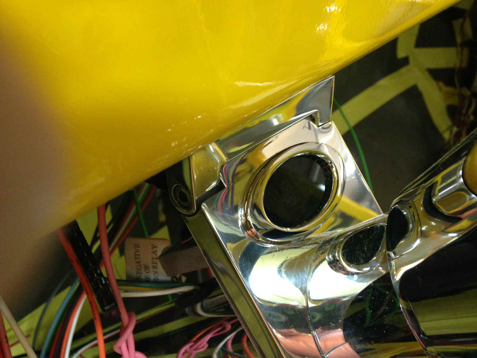
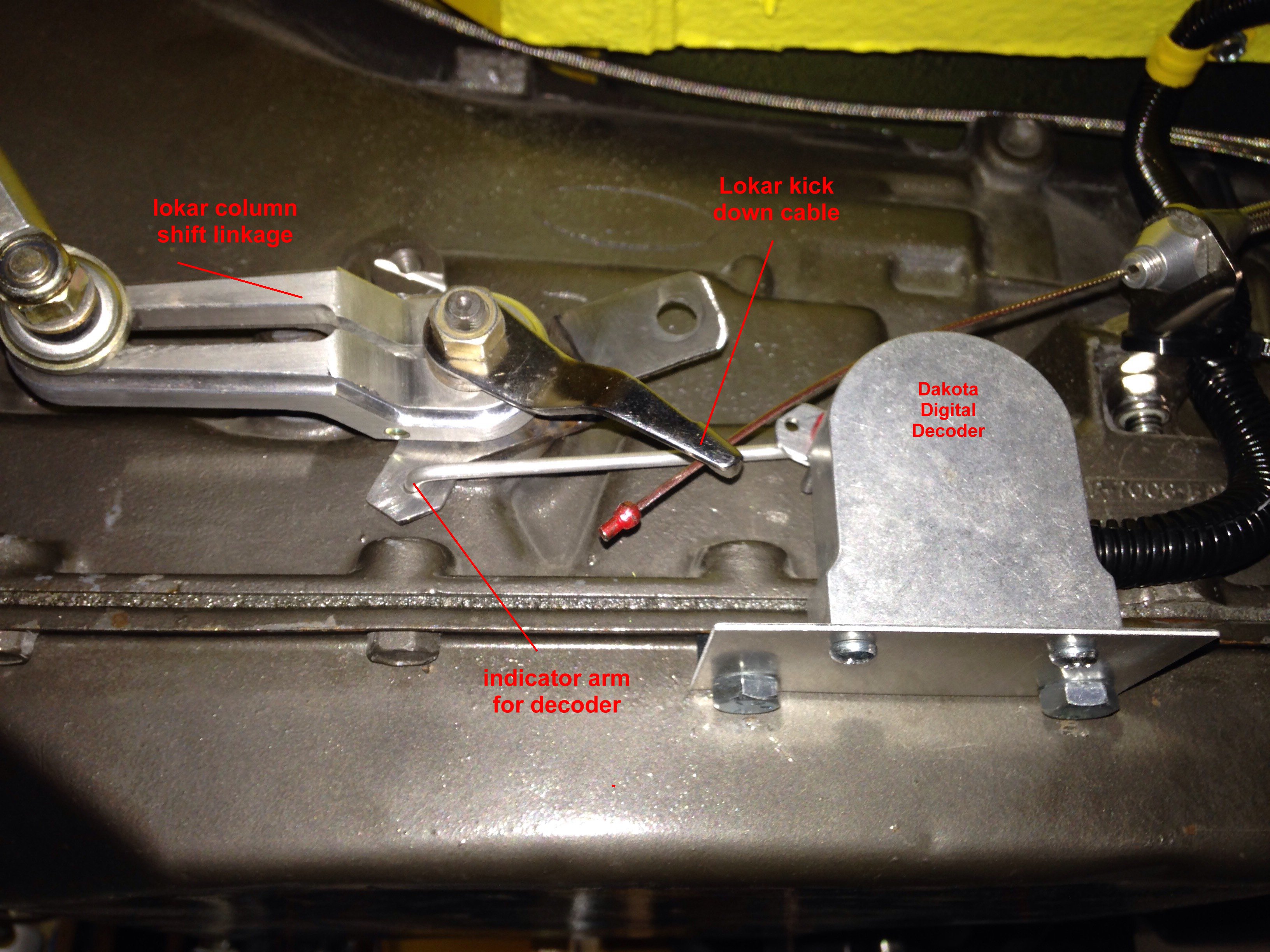
| Here's a
pic of the sending and head unit installed. (the head unit is crooked, I've redrilled it
and got it level...trying to lay in the floor and drill a hole way up under the dash is a
little difficult for an old dude with bad shoulders) My original Ford shift arm had
been cut off and I spent quite a while trying to make the Dakota aluminum arm
work..., no luck, there was no way to make it stay in position and I had no way to bolt
it...so I had to fab up a duplicate of the Dakota C-6 aluminum arm so I could weld it to
the shortened original. Once I did that and changed the little shift rod,
everything worked properly. There is a three wire cable that connects the sending
unit to the head box. It's routed through plastic loom to the cab. The shift
positions are programmed into the head unit by positioning the Lokar shift linkage in each
gear position then pressing the program button for the corresponding gear on the head
unit... corresponding lights on the head unit make it very simple.
|
|||||
|
|||||
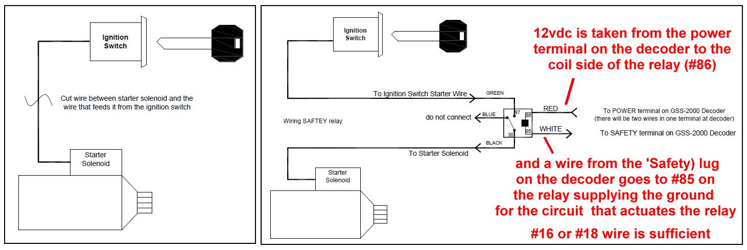
| Since
the original plan didn't include these toys I had to back up and re do some wiring,
routing the ignition switch to solenoid wiring from a direct run to a detour through a
relay that actuated the solenoid only IF the truck was in Park or Neutral. Here's
the circuit layout for the neutral safety switch relay circuit straight out of the DD
instruction book.
|
|||||
|
|||||
| The
decoder also included a 15 amp circuit control for backup lamps so that wiring had to be
re-routed also. Not a major deal since I had several points where I could cut the
original circuit and change course. I eliminated the harness wiring for BU lights
and ran directly from the DD head unit to the lights. The harness wiring was rolled
up and stashed up under the dash for some future expansion if I need it. I
also eliminated the fan power line (pulled power directly off battery...double fused and
relayed) , the alternator exciter wire, the trunk light line and a couple of others I
can't remember now..., I have lots of circuits left for expansion if needed.
|
|||||
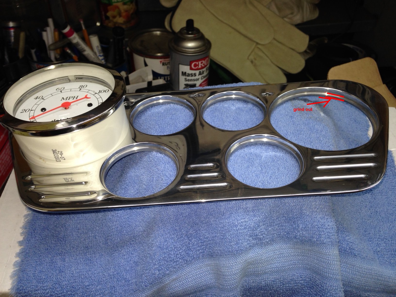
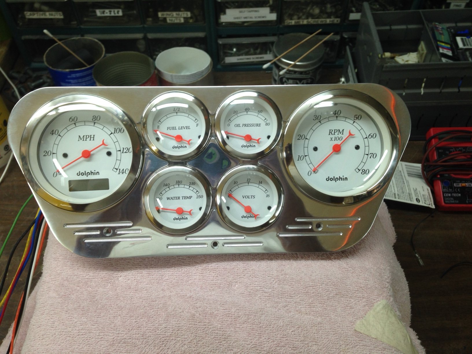
| I've hit
a snag as I wanted to start installing the gauges and dash panel. I bought the panel
in 2000 (yeah, I know) and it was for 3-1/8" speedo and tach. My dolphins are
3-3/8" and won't fit. I'm talking to Mid-50 now trying to work a swap for the
panel with the larger holes. Dolphin was just cranking up production back in 2000
and there probably wasn't a panel in 3-3/8 yet. That's what I get for dragging this
project over decades.
|
|||||
|
|||||
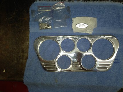
| Well, Mid-50 came through with a duplicate panel that fits the 3-3/8" gauges from Dolphin. These folks are great to deal with... no charge to swap and free shipping .... and here's what they look like. | |||||
|
|||||
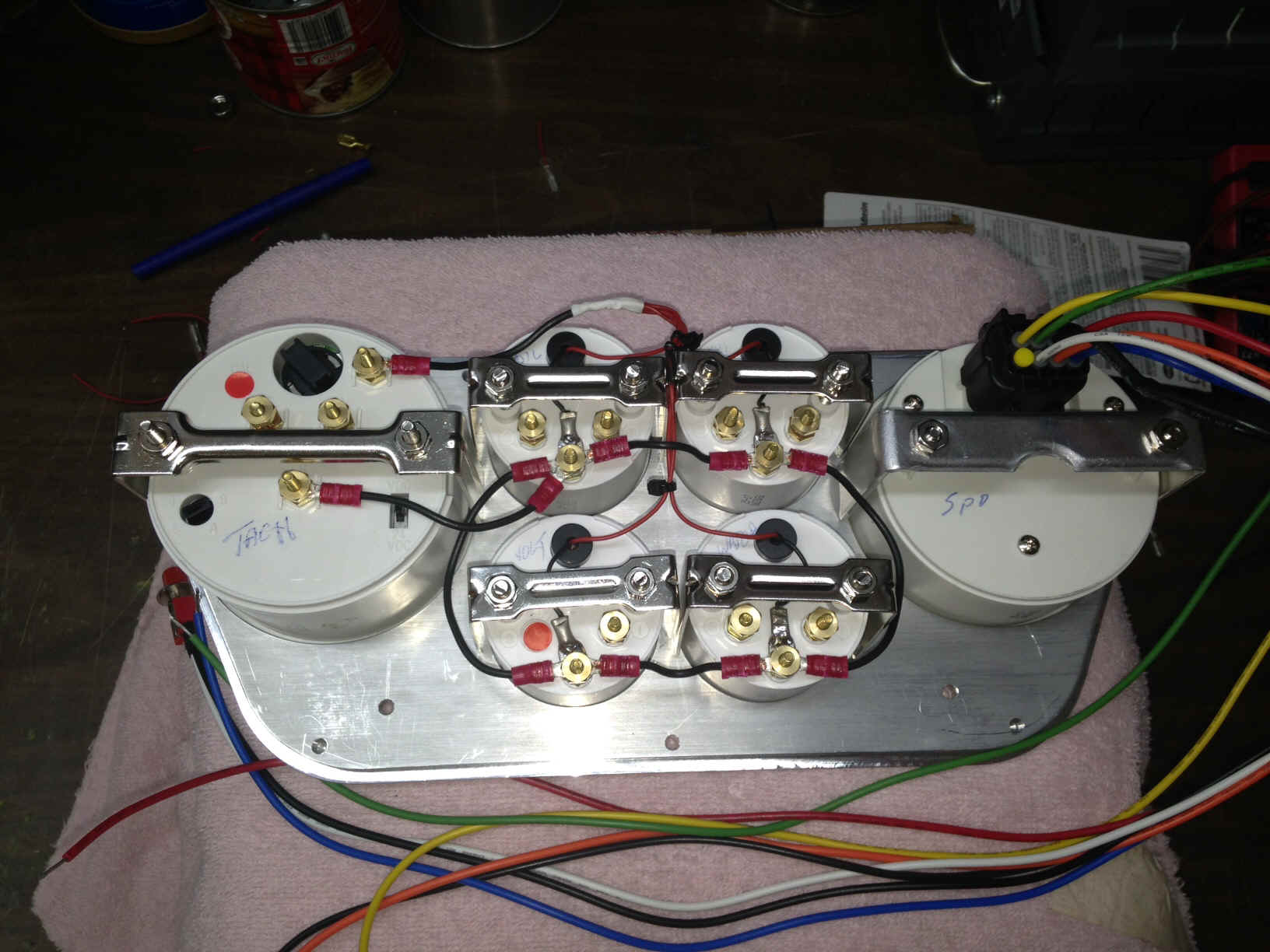
| and the wiring has begun | |||||
|
|||||
| It's
gonna get a little more crowded on the back. I'm going to use Molex 9 pin connectors to
make the dash panel removable, probably two of them .. I'm gonna need 12v
switched power, eng temp, oil pressure, left turn, right turn, dimmer, dash lights, fuel
level, voltage, tach... and there are 8 wires that go to the speedometer... although some
can be combined with the others (12v switched, ground,etc) I'm waiting on the turn signal indicator and hi beam leds in the mail... thought those would be included...not... but hey, Amazon gotta work too. there are several things
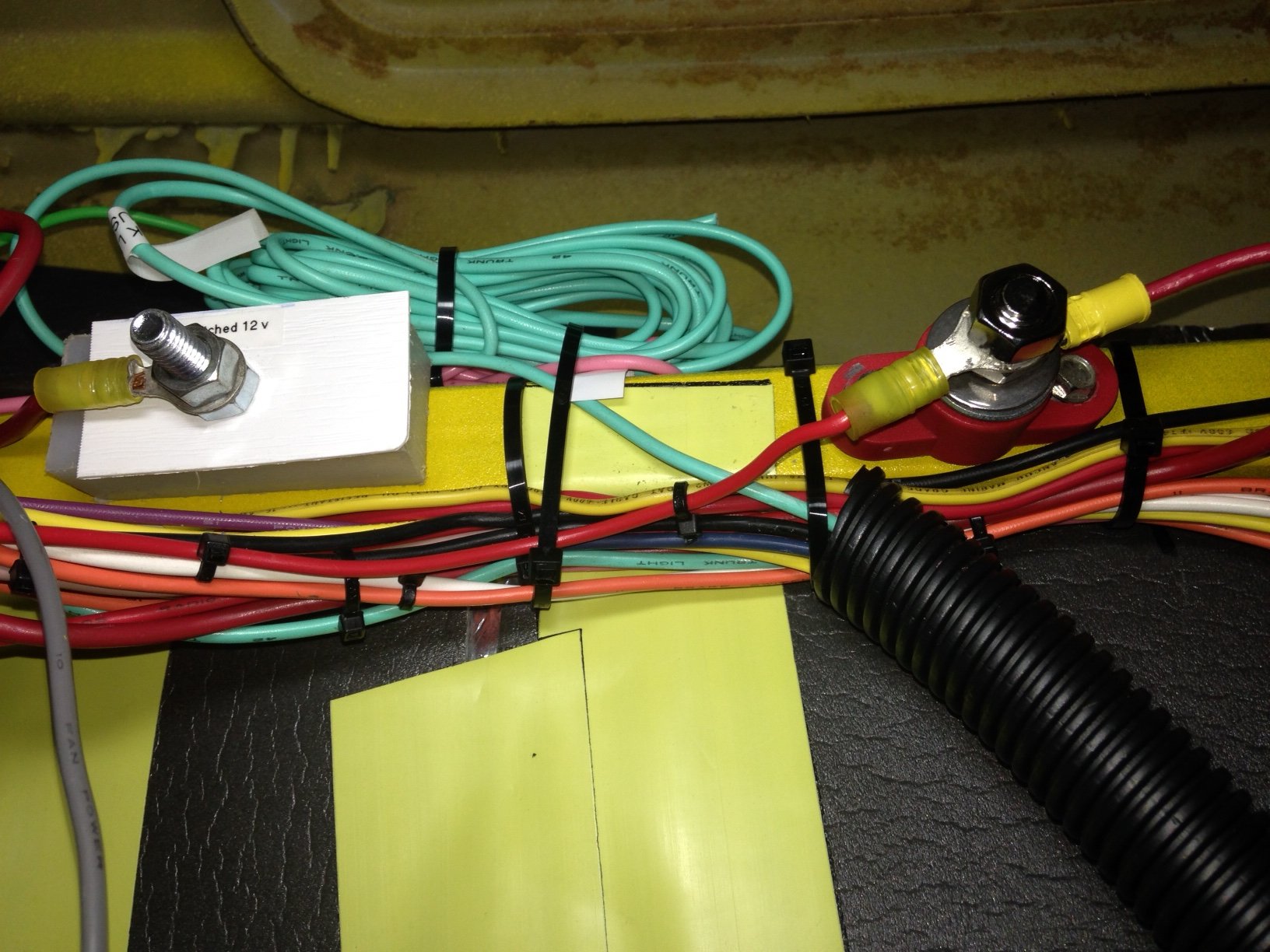
behind the dash that require 12 vdc switched (acc or ignition on) I only have three
points on the fuse panel for acc voltage so I added a terminal block under the dash where
all these items can get their juice. So, now I have a terminal block for 12 vdc battery
power and 12 vdc switched power.. They are mounted on the cross bar under the dash next to
the transmission gear indicator |
|||||
|
|||||
| I made
up this harness to route all the connections to the Molex connector I'm using.. Got a
little carried away with crimping on the connectors and did both ends !!! well,
that's 9 connectors wasted...
|
|||||
|
|||||
| I made a
list of what connection goes into which hole on the connector and identified each wire in
the harness with dots i.e. . .. ... .... ..... etc on each end. That makes it almost foolproof to get the right wire in the right hole
|
|||||
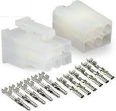
| The
molex connector wiring was pretty simple... it comes with two pieces and the male and
female connectors. You can crimp the connectors with a set of dykes or needle nose
pliers but I'd recommend spending a few bucks and buy the connector pliers made for these
units... much easier and assures a good crimp. There are several good videos behind
YouTube.com that can show you step by step how do do these... I also recommend buying an
'extraction' tool in case you do an uh-ohh.
|
|||||
.jpg)
|
|||||
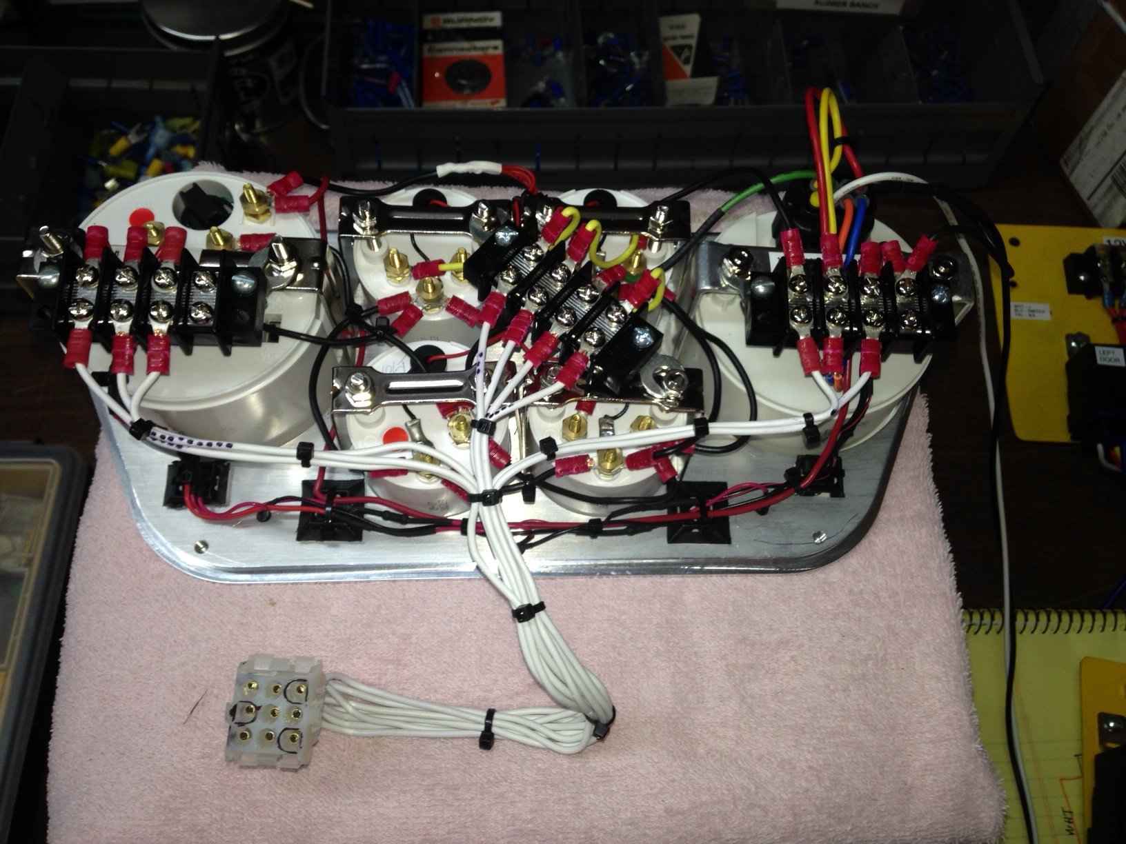
| The dash
panel wiring was straight forward and the harness (above) was married to the Molex
connector and the wires from the components was wired to the other molex and here's the
final product. It's a little busier than the picture above. All of this
neatness isn't absolutely necessary but it helps me keep things in order and find things I
might have missed or connected mistakenly
|
|||||
|
|||||
| You
probably can't see it in this picture but each terminal strip is labeled with what is
connected through it... the close up below shows it... I'd recommend this if you
have the opportunity, it sure saves time and frustration trying to trace things... I've
also labeled a lot of the underside dash wiring.
|
|||||
|
|||||
| Well,
the dash panel was a big chunk of wiring done, so I'm moving on to the relay boards and
the console. Pretty much everything but the light switch and wipers is tied into
console. I've mounted the two relay boards shown above to the inside wall of the
console... it's using wasted space and they are out of the way of other stuff. The
top covers for the console will be removable (probably velcro) to access these boards
(hopefully never) The wiring is a mess here... still have to do all the point to
point stuff here.
|
|||||
|
|||||
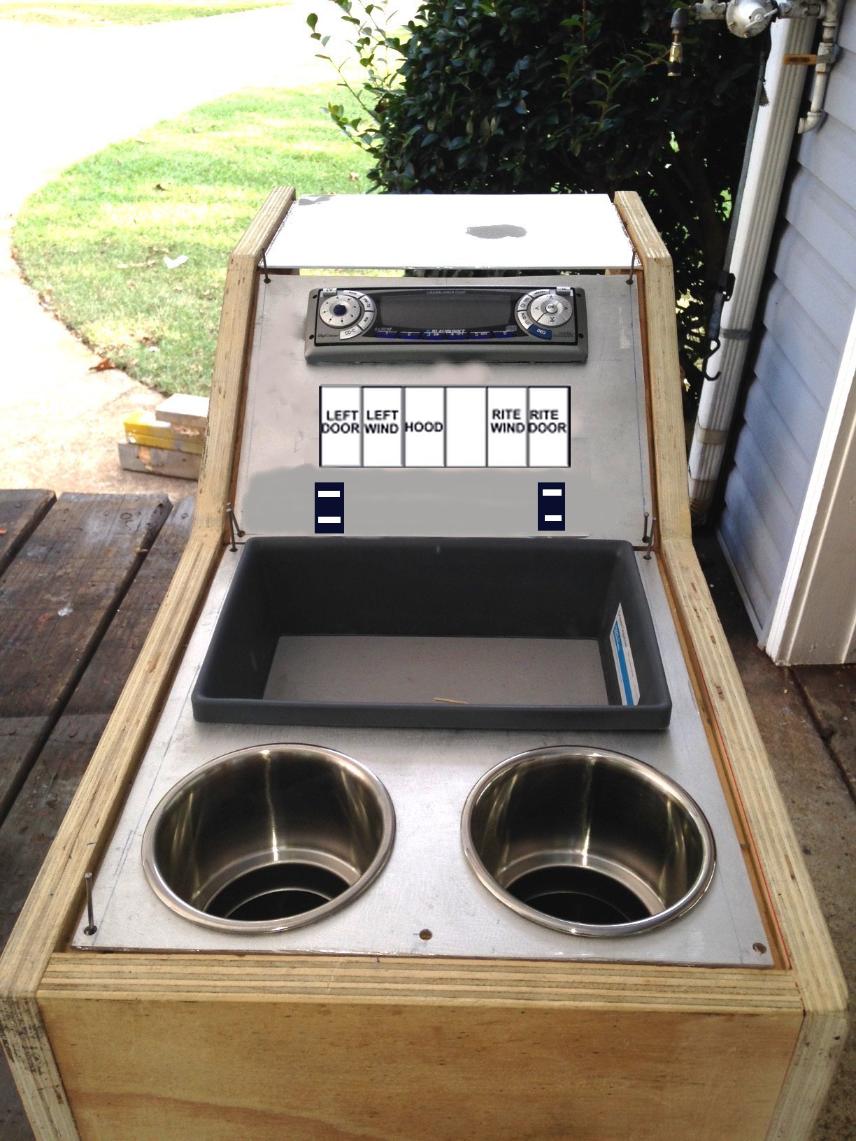
| Here's a mockup of the console showing components and locations. A careful eye will see that the wiring configurations on the panels isn't as shown in the previous pictures... sometimes I overthink myself and have to 're-adjust'. After I installed the panels in the console I tested each board with a boost battery and everything works as it should now.
|
|||||
|
|||||
| At this point, I'm just about done with all the wiring, other than tying in the door,window, hood etc switches inside the console. Since this is my first wandering into the wiring harness installation world, I'm a little apprehensive about just slapping the cables on a battery and watching for smoke. It might be best to remove all the fuses from the fuse panel and buy a handful of switches and try out one circuit at a time. It's probably gonna be a time consuming job but it's safer that way. I'll use my jump battery pack at first and ease into it gently. Worst case scenario is I waste lot of time and everything works as it should... or I use a lot of fuses and fix my problems one at a time . | |||||
|
|
|||||
| Much later in the story... life gets in the way sometimes. So, having finished the majority of the wiring, I moved to other things. There are still some tie-ins to do, but enough is done to make a driver. I'm not going to detail every device install as most are about the same ... positive & negative(ground) and control or switch wiring. If you have gotten this far in the wiring, the rest will be a breeze. All of my console switch wiring (i.e. door and window switches and hood opening closing is just laying in the floor under the console location and if I need to activate something I just jumper it to the ignition switch or one of my 12 volt termination points. Stereo wiring is still to be done but it will probably get done after console install and upholstery.. I've still got to mount speaker panels and such. One thing I did not do and will correct is to install a disconnect at the headlight wiring behind the grill. It's all hard wired and I plan on removing the grill to 'french' in the headlight buckets. So, instead of removing all the wiring, I'll put in a connector I can just unplug for grill removal. | |||||
|
|
|||||
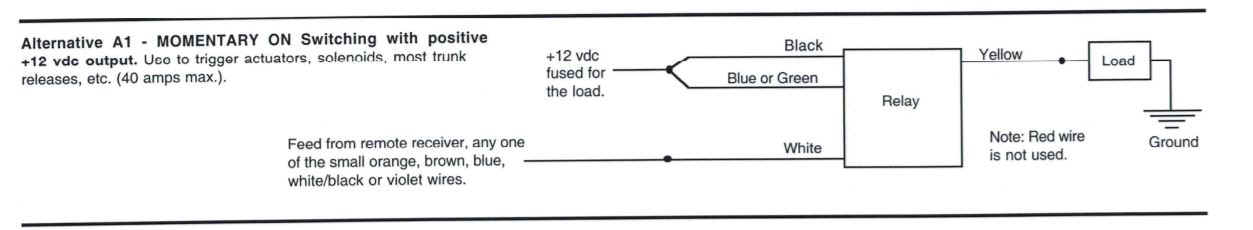
| Edit...
remote door access section added. Some things get
forgotten or fall far down the list. They would have been easier to accomplish back
then... but anyway... Finally remembered that I needed to access the doors from outside
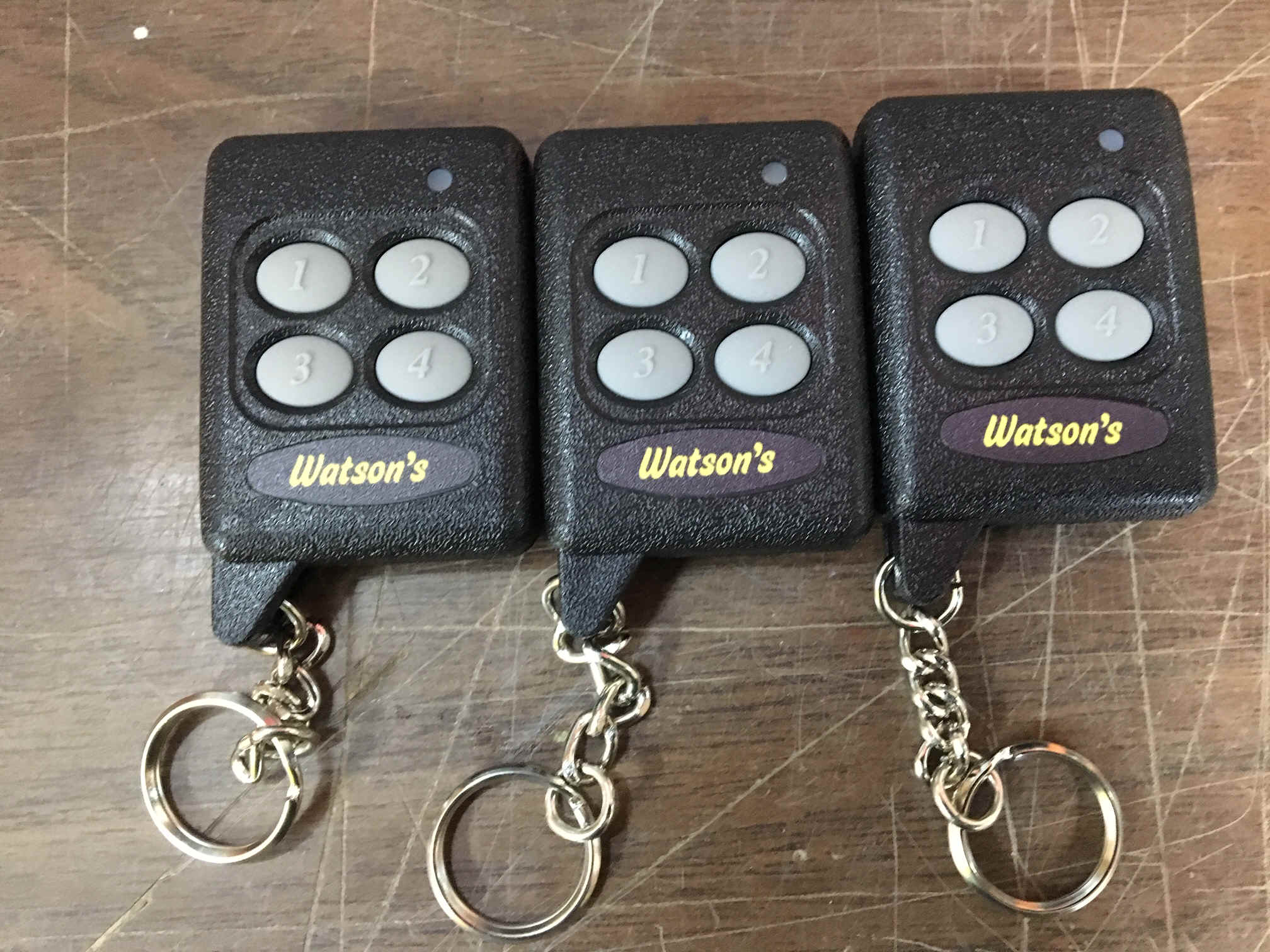
the truck (duh !!). I had previously bought a 7 channel remote access with key
fobs from a fellow builder and of course put it on the shelf (so I wouldn't misplace it)
I got it down and hooked up a 'test' circuit to figure it all out.. well,
guess what ?? It was dead. Don't know if the p.o. killed it or if it was bad
from the factory. Sadly he has passed so there no way to question him and the ebay
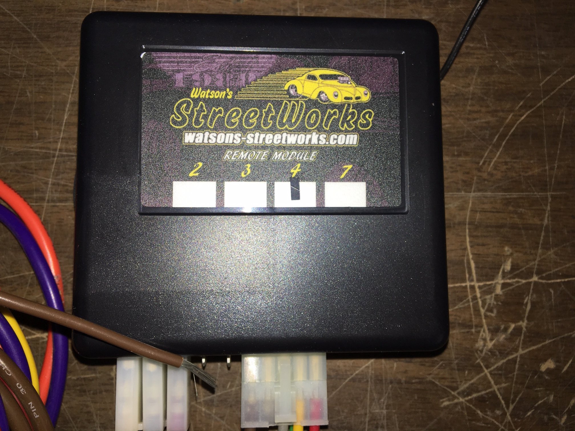
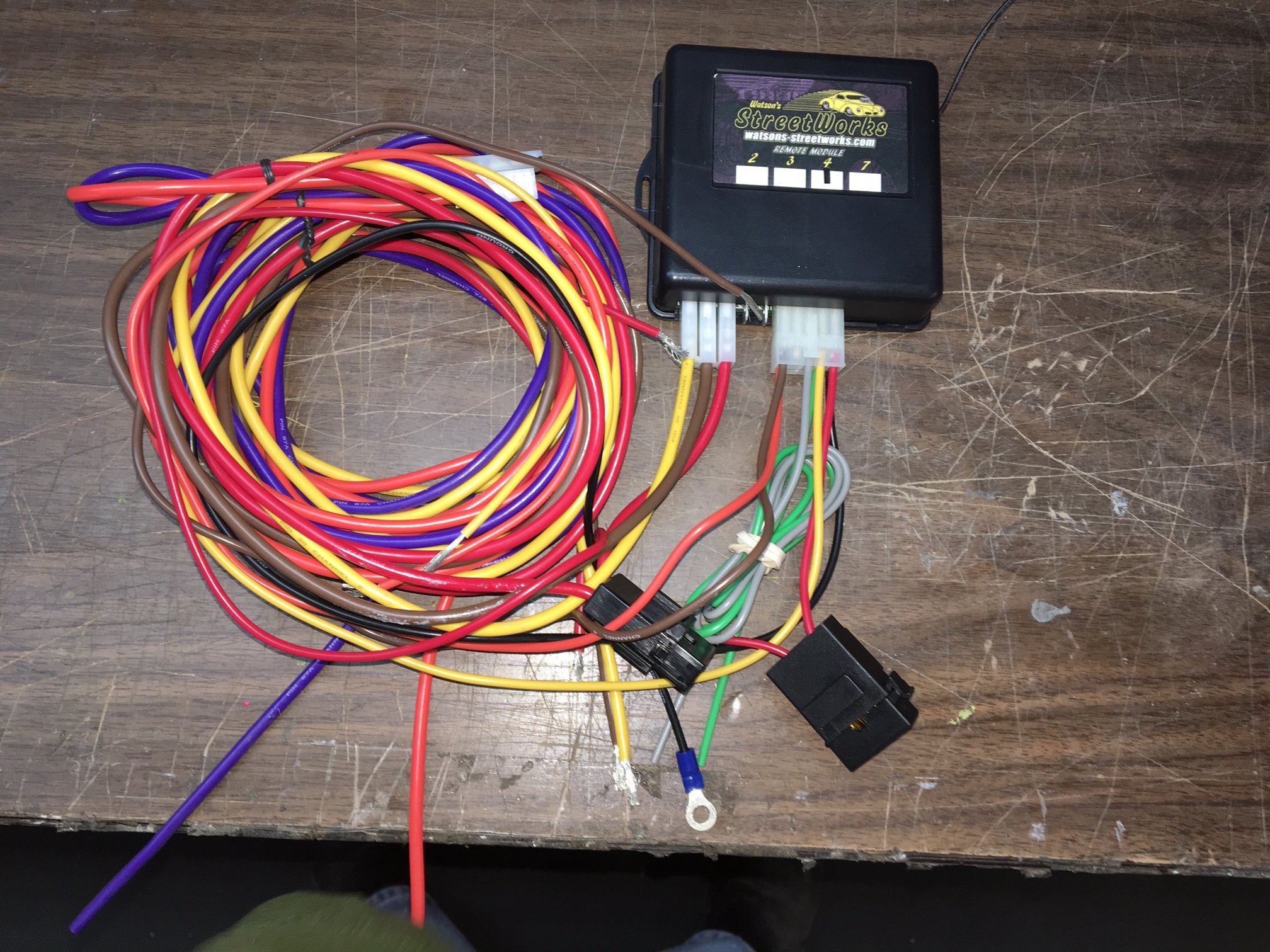
guy wouldn't even talk to me. I found another 4 channel unit from Watson's Street
works and the brown truck brought it quickly. They provide excellent instructions
that even a dummy like me could read... now, understanding them ??? several
phone calls with questions kept me going in the right direction. Their tech guys are
patient and very knowledgable. I hooked up my test board and with 30 or so jumper
wires I got the left door then the right door sorted out and figured out how to parallel
their feed to the manual switch feed to open the doors. I was going to use one of
the other two channels for the hood. During a call to Watsons I was told that it
would take two circuits... one for up and one for down.. not a problem since I had two
empty. I also found out that channel 3 & 4 output a negative signal.
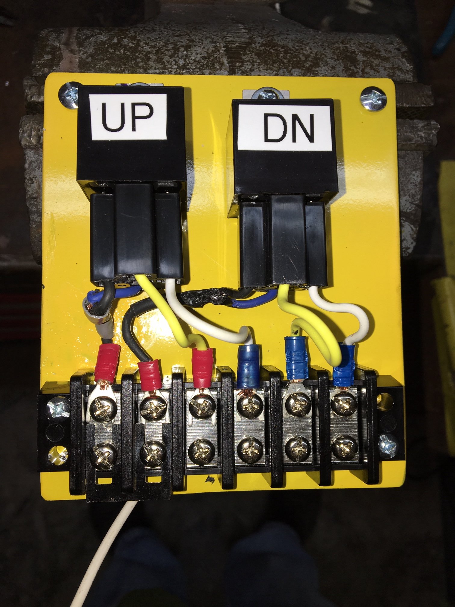
Hmmm.. I'm switching positive voltage on my hood relays. My only answer
without rewiring the existing circuit was to add an ADDITIONAL set of relays to use a
negative signal to switch a positive voltage to my existing relays. Well that got in
my head a little but I finally found and figured out Watson's diagram and got it done. It
took two relays, one for up (channel 3) and one for down (channel 4)
|
|||||
|
|||||
|
|
|
|
||
| So all
of this extra wiring was added into the console and appropriate wiring was run from the
relay terminal strip to the output of the manual switches already installed... it's
getting crowded in there. This really will be cleaned up before installation
in the truck.. I don't know exact wire lengths to some thing just yet... Test fit in the
truck will determine it and much and many wire ties and clamps will be added.
|
|||||
|
|||||
| Boilerplate denial of liability statement… i.e. the fine print |
|||||